


13 - 75
Chapter 13 Control Sub Functions
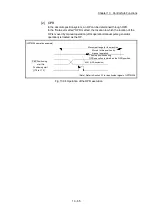
13.7.3 M code output function
The "M code output function" is used to command sub work (clamping, drill rotation,
tool replacement, etc.) related to the positioning data being executed.
When the M code ON signal is turned ON during positioning execution, a No. called
the M code is stored in "
Md.25
Valid M code
". These "
Md.25
Valid M code
" are read from
the PLC CPU, and used to command auxiliary work. M codes can be set for each
positioning data. (Set in setting item "
Da.10
M code/Condition data No./Number of LOOP
to LEND repetitions
" of the positioning data.)
The timing for outputting (storing) the M codes can also be set in the "M code output
function".
Signal
LD77MS2/LD77MS4
LD77MS16
M code ON signal
X4, X5, X6, X7
M code ON (
Md.31
Status
: b12)
The details shown below explain about the "M code output function".
[1] M code ON signal output timing
[2] M code ON signal OFF request
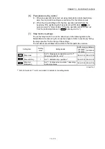
[3] Precautions during control
[4] Setting the M code output function
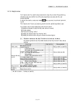
[5] Reading M codes
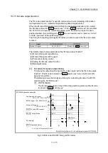
[1] M code ON signal output timing
The timing for outputting (storing) the M codes can be set in the "M code output
function". (The M code is stored in "
Md.25
Valid M code
" when the M code ON
signal is turned ON.)
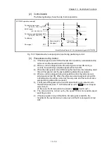
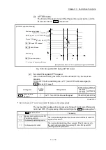
The following shows the two types of timing for outputting M codes: the "WITH
mode" and the "AFTER mode".
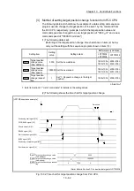
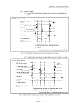
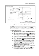
(1) WITH mode
The M code ON signal is turned ON at the positioning start, and the M code
is stored in "
Md.25
Valid M code
".
[LD77MS4 operation example]
Md. 25 Valid M code
Cd. 7 M code OFF request
Positioning start signal
BUSY signal
M code ON signal
Positioning
01
00
m1
m2
1: m1 and m2 indicate set M codes.
Dwell time
V
t
1 0
1 0
0
0
OFF
OFF
OFF
ON
ON
Da. 1 Operation pattern
[XC, XD, XE, XF]
[Y10, Y11, Y12, Y13]
[X4, X5, X6, X7]
ON
1
1
(Note): Refer to Section 3.3 for input/output signal of LD77MS16.
Fig. 13.38 M code ON/OFF timing (WITH mode)
Summary of Contents for MELSEC-L Series
Page 2: ......
Page 30: ...MEMO ...
Page 70: ...2 10 Chapter 2 System Configuration MEMO ...
Page 83: ...3 13 Chapter 3 Specifications and Functions MEMO ...
Page 103: ...3 33 Chapter 3 Specifications and Functions MEMO ...
Page 107: ...3 37 Chapter 3 Specifications and Functions MEMO ...
Page 111: ...3 41 Chapter 3 Specifications and Functions MEMO ...
Page 115: ...3 45 Chapter 3 Specifications and Functions MEMO ...
Page 140: ...4 22 Chapter 4 Installation Wiring and Maintenance of the Product MEMO ...
Page 253: ...5 113 Chapter 5 Data Used for Positioning Control MEMO ...
Page 342: ...5 202 Chapter 5 Data Used for Positioning Control MEMO ...
Page 438: ...7 20 Chapter 7 Memory Configuration and Data Process MEMO ...
Page 440: ...MEMO ...
Page 485: ...9 25 Chapter 9 Major Positioning Control MEMO ...
Page 594: ...9 134 Chapter 9 Major Positioning Control MEMO ...
Page 624: ...10 30 Chapter 10 High Level Positioning Control MEMO ...
Page 656: ...11 32 Chapter 11 Manual Control MEMO ...
Page 690: ...12 34 Chapter 12 Expansion Control MEMO ...
Page 798: ...13 108 Chapter 13 Control Sub Functions MEMO ...
Page 866: ...14 68 Chapter 14 Common Functions MEMO ...
Page 884: ...15 18 Chapter 15 Dedicated Instructions MEMO ...
Page 899: ...16 15 Chapter 16 Troubleshooting MEMO ...
Page 1036: ...Appendix 88 Appendices MEMO ...
Page 1039: ......


