


16 - 33
Chapter 16 Troubleshooting
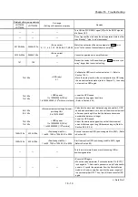
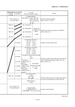
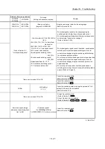
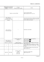
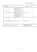
Related buffer memory address
Set range
(Setting with sequence program)
Remedy
LD77MS2
LD77MS4
LD77MS16
Refer to Section 5.3
"List of positioning data"
<Maximum radius>
536870912
Correct the positioning data.
(Refer to Section 9.2.10 or 9.2.11)
<LOOP to LEND>
1 to 65535
Set 1 to 65535 in the repeating time of LOOP. (Refer to
Section 9.2.22)
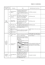
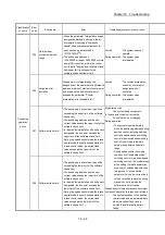
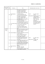
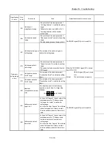
ABS setting direction in the unit
of degree
0: Shortcut
1: Clockwise
2: Counterclockwise
• Set the ABS setting direction in the unit of degree within the
setting range.
• Set "0" when the software stroke limits are valid. (Refer to
Section 9.1.5)
1550+100n 4350+100n
Software stroke limit
upper limit
• [mm] [inch] [PLS]
–2147483648 to 2147483647
• [degree]
0 to 35999999
Invalidate the software stroke limit.
(To invalidate, set the software stroke limit upper limit value to
the software stroke limit lower limit value.)
(Refer to Section 9.1.5)
18+150n
19+150n
Software stroke limit
lower limit
20+150n
21+150n
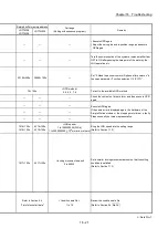
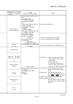
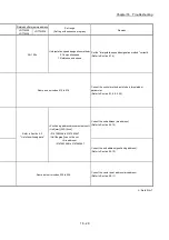
Operation setting for
incompletion of OPR
<Operation setting for incompletion of
OPR>
0, 1
• Start after the OPR is executed.
• Switch the control mode after the OPR is executed.
• For systems which can operate the positioning control and
speed-torque control though the OPR request is ON, set "1"
to the setting value of the operation setting at OPR
incomplete.
87+150n
— —
—
Use a servo amplifier which supports the continuous operation
to torque control.
1594+100n
1595+100n
4394+100n
4395+100n
< Outside control mode auto-shift
switching parameter range >
When "1" or "2" is set in "
Cd.153
Control
mode auto-shift selection
".
• [mm] [inch] [PLS]
–2147483648 to 2147483647
• [degree]
0 to 35999999
Set the control mode auto-shift switching parameter within the
range and switch to the continuous operation to torque control
mode.
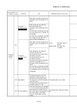
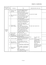
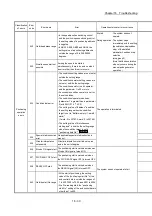
— —
—
Clear the setting of the CPU module parameter "Output at
error stop".
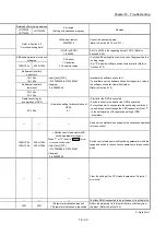
—
—
—
The flash ROM is expected to be at the end of its writable life.
1901 5901
<Parameter initialization request>
1: Parameter initialization is requested
Return the parameter to that set at the time of delivery from
the plant. (Refer to Section 14.2)
n: Axis No.-1
Summary of Contents for MELSEC-L Series
Page 2: ......
Page 30: ...MEMO ...
Page 70: ...2 10 Chapter 2 System Configuration MEMO ...
Page 83: ...3 13 Chapter 3 Specifications and Functions MEMO ...
Page 103: ...3 33 Chapter 3 Specifications and Functions MEMO ...
Page 107: ...3 37 Chapter 3 Specifications and Functions MEMO ...
Page 111: ...3 41 Chapter 3 Specifications and Functions MEMO ...
Page 115: ...3 45 Chapter 3 Specifications and Functions MEMO ...
Page 140: ...4 22 Chapter 4 Installation Wiring and Maintenance of the Product MEMO ...
Page 253: ...5 113 Chapter 5 Data Used for Positioning Control MEMO ...
Page 342: ...5 202 Chapter 5 Data Used for Positioning Control MEMO ...
Page 438: ...7 20 Chapter 7 Memory Configuration and Data Process MEMO ...
Page 440: ...MEMO ...
Page 485: ...9 25 Chapter 9 Major Positioning Control MEMO ...
Page 594: ...9 134 Chapter 9 Major Positioning Control MEMO ...
Page 624: ...10 30 Chapter 10 High Level Positioning Control MEMO ...
Page 656: ...11 32 Chapter 11 Manual Control MEMO ...
Page 690: ...12 34 Chapter 12 Expansion Control MEMO ...
Page 798: ...13 108 Chapter 13 Control Sub Functions MEMO ...
Page 866: ...14 68 Chapter 14 Common Functions MEMO ...
Page 884: ...15 18 Chapter 15 Dedicated Instructions MEMO ...
Page 899: ...16 15 Chapter 16 Troubleshooting MEMO ...
Page 1036: ...Appendix 88 Appendices MEMO ...
Page 1039: ......


