


11 - 7
Chapter 11 Manual Control
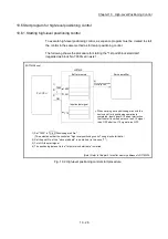
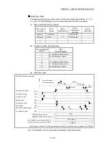
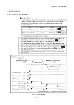
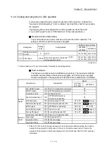
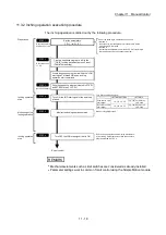
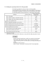
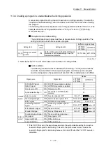
11.2.2 JOG operation execution procedure
The JOG operation is carried out by the following procedure.
STEP 1
Preparation
Refer to Chapter 5
and Section 11.2.3.
End of control
STEP 2
Refer to Section
11.2.4.
STEP 3
Turn ON the JOG start signal.
STEP 4
Monitor using GX Works2.
STEP 5
Write the sequence program created in STEP1
and STEP2 to the PLC CPU.
Turn ON the JOG start signal of the axis to be
started.
Monitoring of the
JOG operation
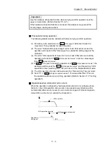
Stop the JOG operation when the JOG start signal is turned
OFF using the sequence program in STEP 2.
STEP 6
Turn OFF the JOG start signal that is ON.
Monitor the JOG operation status.
Refer to Chapter 6.
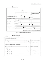
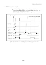
JOG operation
start
JOG operation
stop
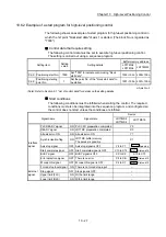
Set the parameters.
( to )
Pr.1
Pr.39
One of the following two methods can be used.
<Method 1>
Directly set (write) the parameters in the Simple Motion
module using GX Works2.
<Method 2>
Set (write) the parameters from the PLC CPU to the Simple
Motion module using the sequence program.
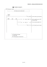
Create a sequence program for the following
setting.
Set a "0" in " Inching movement amount".
Cd.16
Cd.17
Set the " JOG speed". (Control data
setting)
Create a sequence program in which the "JOG
start signal" is turned ON by a JOG operation
start command.
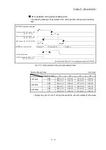
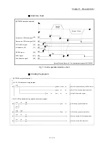
LD77MS2/LD77MS4
Y8, YA, YC, YE
Y9, YB, YD, YF
Forward run JOG
start signal
Reverse run JOG
start signal
LD77MS16
Cd.181 Forward run
JOG start
Cd.182 Reverse run
JOG start
REMARK
Mechanical elements such as limit switches are considered as already installed.
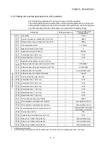
Parameter settings work in common for all control using the Simple Motion module.
Summary of Contents for MELSEC-L Series
Page 2: ......
Page 30: ...MEMO ...
Page 70: ...2 10 Chapter 2 System Configuration MEMO ...
Page 83: ...3 13 Chapter 3 Specifications and Functions MEMO ...
Page 103: ...3 33 Chapter 3 Specifications and Functions MEMO ...
Page 107: ...3 37 Chapter 3 Specifications and Functions MEMO ...
Page 111: ...3 41 Chapter 3 Specifications and Functions MEMO ...
Page 115: ...3 45 Chapter 3 Specifications and Functions MEMO ...
Page 140: ...4 22 Chapter 4 Installation Wiring and Maintenance of the Product MEMO ...
Page 253: ...5 113 Chapter 5 Data Used for Positioning Control MEMO ...
Page 342: ...5 202 Chapter 5 Data Used for Positioning Control MEMO ...
Page 438: ...7 20 Chapter 7 Memory Configuration and Data Process MEMO ...
Page 440: ...MEMO ...
Page 485: ...9 25 Chapter 9 Major Positioning Control MEMO ...
Page 594: ...9 134 Chapter 9 Major Positioning Control MEMO ...
Page 624: ...10 30 Chapter 10 High Level Positioning Control MEMO ...
Page 656: ...11 32 Chapter 11 Manual Control MEMO ...
Page 690: ...12 34 Chapter 12 Expansion Control MEMO ...
Page 798: ...13 108 Chapter 13 Control Sub Functions MEMO ...
Page 866: ...14 68 Chapter 14 Common Functions MEMO ...
Page 884: ...15 18 Chapter 15 Dedicated Instructions MEMO ...
Page 899: ...16 15 Chapter 16 Troubleshooting MEMO ...
Page 1036: ...Appendix 88 Appendices MEMO ...
Page 1039: ......


