


11 - 16
Chapter 11 Manual Control
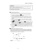
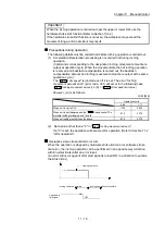
Important
When the inching operation is carried out near the upper or lower limit, use the
hardware stroke limit function (Refer to Section 13.4.4).
If the hardware stroke limit function is not used, the workpiece may exceed the
movement range, and an accident may result.
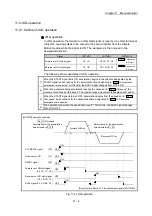
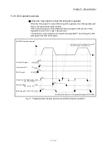
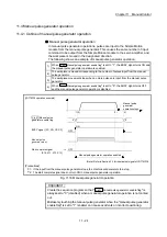
Precautions during operation
The following details must be understood before inching operation is carried out.
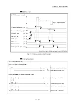
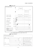
(1) Acceleration/deceleration processing is not carried out during inching
operation.
(Commands corresponding to the designated inching movement amount are
output at operation cycle. When the movement direction of inching operation
is reversed and backlash compensation is carried out, the backlash
compensation amount and inching movement amount are output at the same
operation cycle.)
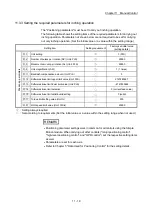
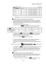
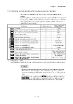
The "
Cd.17
JOG speed
" is ignored even if it is set. The error "Inching
movement amount error" (error code: 301) will occur in the following case.
(
Cd.16
Inching movement amount
) x (A) > (
Pr.31
JOG speed limit value
)
However, (A) is as follows.
Unit: [ms]
Operation cycle
0.88 1.77
When unit is set to PLS
1125
562.5
When unit is set to degree and the "
Pr.83
Speed control 10 x
multiplier setting for degree axis" is valid
67.5 33.75
When unit setting is other than the above
675
337.5
(2) Set a value other than a "0" in "
Cd.16
Inching movement amount
".
If a "0" is set, the operation will become JOG operation (Refer to Section 11.2
"JOG operation").
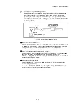
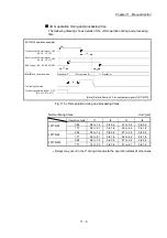
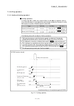
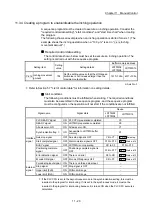
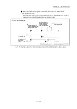
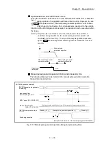
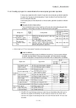
Operations when stroke limit error occurs
When the operation is stopped by hardware stroke limit error or software stroke
limit error, the inching operation can be performed in an opposite way (direction
within normal limits) after an error reset.
(An error will occur again if JOG start signal is turned ON in a direction to outside
the stroke limit.)
Inching operation possible
Upper/lower
limit signal
Inching operation
V
Inching operation not possible
ON
OFF
Summary of Contents for MELSEC-L Series
Page 2: ......
Page 30: ...MEMO ...
Page 70: ...2 10 Chapter 2 System Configuration MEMO ...
Page 83: ...3 13 Chapter 3 Specifications and Functions MEMO ...
Page 103: ...3 33 Chapter 3 Specifications and Functions MEMO ...
Page 107: ...3 37 Chapter 3 Specifications and Functions MEMO ...
Page 111: ...3 41 Chapter 3 Specifications and Functions MEMO ...
Page 115: ...3 45 Chapter 3 Specifications and Functions MEMO ...
Page 140: ...4 22 Chapter 4 Installation Wiring and Maintenance of the Product MEMO ...
Page 253: ...5 113 Chapter 5 Data Used for Positioning Control MEMO ...
Page 342: ...5 202 Chapter 5 Data Used for Positioning Control MEMO ...
Page 438: ...7 20 Chapter 7 Memory Configuration and Data Process MEMO ...
Page 440: ...MEMO ...
Page 485: ...9 25 Chapter 9 Major Positioning Control MEMO ...
Page 594: ...9 134 Chapter 9 Major Positioning Control MEMO ...
Page 624: ...10 30 Chapter 10 High Level Positioning Control MEMO ...
Page 656: ...11 32 Chapter 11 Manual Control MEMO ...
Page 690: ...12 34 Chapter 12 Expansion Control MEMO ...
Page 798: ...13 108 Chapter 13 Control Sub Functions MEMO ...
Page 866: ...14 68 Chapter 14 Common Functions MEMO ...
Page 884: ...15 18 Chapter 15 Dedicated Instructions MEMO ...
Page 899: ...16 15 Chapter 16 Troubleshooting MEMO ...
Page 1036: ...Appendix 88 Appendices MEMO ...
Page 1039: ......


