


5 - 33
Chapter 5 Data Used for Positioning Control
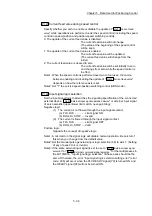
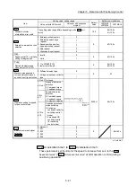
Pr.14
Software stroke limit selection
Set whether to apply the software stroke limit on the "current feed value" or the
"machine feed value". The software stroke limit will be validated according to the
set value.
To invalidate the software stroke limit, set the setting value to "current feed value".
When "2: degree" is set in "
Pr.1 Unit setting", set the setting value of software
stroke limit to "current feed value".
The error "Software stroke limit selection" (error code: 923) will occur if "machine
feed value" is set.
Pr.15
Software stroke limit valid/invalid setting
Set whether to validate the software stroke limit during JOG/Inching operation and
manual pulse generator operation.
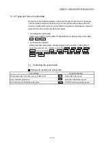
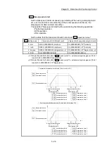
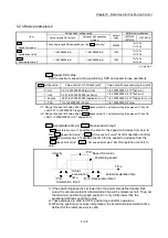
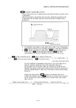
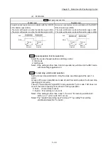
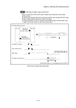
Pr.16
Command in-position width
Set the remaining distance that turns the command in-position ON. The command
in-position signal is used as a front-loading signal of the positioning complete
signal. When positioning control is started, the "Command in-position flag (
Md.31
Status: b2)" turns OFF, and the "command in-position flag" turns ON at the set
position of the command in-position signal.
ON
OFF
Pr.16
Command in-position width
Velocity
Position control start
Command
in-position flag
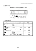
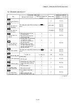
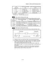
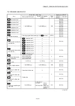
Pr.1
setting value
Value set with GX Works2
(unit)
Value set with sequence program
(unit)
0 : mm
0.1 to 214748364.7 (µm)
1 to 2147483647 (×10
–1
µm)
1 : inch
0.00001 to 21474.83647 (inch)
1 to 2147483647 (×10
–5
inch)
2 : degree
0.00001 to 21474.83647 (degree)
1 to 2147483647 (×10
–5
degree)
3 : PLS
1 to 2147483647 (PLS)
1 to 2147483647 (PLS)
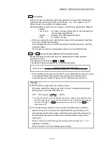
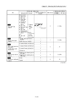
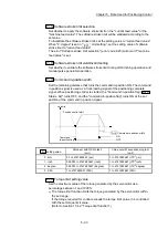
Pr.17
Torque limit setting value
Set the maximum value of the torque generated by the servomotor as a
percentage between 1 and 1000%.
The torque limit function limits the torque generated by the servomotor within
the set range.
If the torque required for control exceeds the torque limit value, it is controlled
with the set torque limit value.
(Refer to Section 13.4.2 "Torque limit function".)
Summary of Contents for MELSEC-L Series
Page 2: ......
Page 30: ...MEMO ...
Page 70: ...2 10 Chapter 2 System Configuration MEMO ...
Page 83: ...3 13 Chapter 3 Specifications and Functions MEMO ...
Page 103: ...3 33 Chapter 3 Specifications and Functions MEMO ...
Page 107: ...3 37 Chapter 3 Specifications and Functions MEMO ...
Page 111: ...3 41 Chapter 3 Specifications and Functions MEMO ...
Page 115: ...3 45 Chapter 3 Specifications and Functions MEMO ...
Page 140: ...4 22 Chapter 4 Installation Wiring and Maintenance of the Product MEMO ...
Page 253: ...5 113 Chapter 5 Data Used for Positioning Control MEMO ...
Page 342: ...5 202 Chapter 5 Data Used for Positioning Control MEMO ...
Page 438: ...7 20 Chapter 7 Memory Configuration and Data Process MEMO ...
Page 440: ...MEMO ...
Page 485: ...9 25 Chapter 9 Major Positioning Control MEMO ...
Page 594: ...9 134 Chapter 9 Major Positioning Control MEMO ...
Page 624: ...10 30 Chapter 10 High Level Positioning Control MEMO ...
Page 656: ...11 32 Chapter 11 Manual Control MEMO ...
Page 690: ...12 34 Chapter 12 Expansion Control MEMO ...
Page 798: ...13 108 Chapter 13 Control Sub Functions MEMO ...
Page 866: ...14 68 Chapter 14 Common Functions MEMO ...
Page 884: ...15 18 Chapter 15 Dedicated Instructions MEMO ...
Page 899: ...16 15 Chapter 16 Troubleshooting MEMO ...
Page 1036: ...Appendix 88 Appendices MEMO ...
Page 1039: ......


