


4 - 18
Chapter 4 Installation, Wiring and Maintenance of the Product
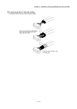
[3] Precautions for FG terminal wiring
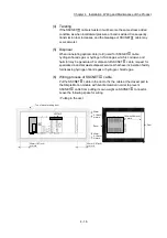
(1) Wiring
Use the thickest wires (Up to 1.31mm
2
) possible to reduce the voltage drop
to the minimum for the FG cable of the Simple Motion module.
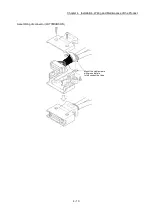
Use the wires of the following core size and crimping terminal for wiring.
(a) Ground wire
Application
Recommended core size
AWG
(Note-1)
Ground wire
0.517 to 1.31 mm
2
AWG20 to AWG16
(b) Crimping terminal
Applicable name
Recommended core size
AWG
(Note-1)
RAV1.25-3
0.517 to 1.31 mm
2
AWG20 to AWG16
(Note-1): AWG stands for "American Wire Gauge". AWG is a unit of the thickness of conducting wire.
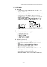
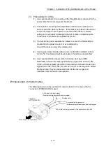
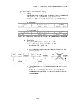
(2) Grounding
For grounding, follow the steps (a) to (c) shown below.
(a) Use a dedicated grounding wire as far as possible.
(Ground resistance: 100
or less)
(b) When a dedicated grounding cannot be performed, use 2) Common
grounding shown below.
LD77MS
L61P
Another
equipment
LD77MS
L61P
Another
equipment
LD77MS
L61P
Another
equipment
Grounding
1) Independent grounding.....Best
Grounding
2) Common grounding.....Good
3) Joint grounding.....Not allowed
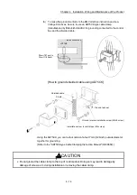
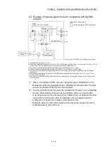
(c) For grounding a cable, use the cable of AWG20 to AWG16 (0.517 to
1.31 mm
2
).
Position the ground-contact point as nearly to the Simple Motion
module as possible, and reduce the length of the grounding cable as
much as possible.
Summary of Contents for MELSEC-L Series
Page 2: ......
Page 30: ...MEMO ...
Page 70: ...2 10 Chapter 2 System Configuration MEMO ...
Page 83: ...3 13 Chapter 3 Specifications and Functions MEMO ...
Page 103: ...3 33 Chapter 3 Specifications and Functions MEMO ...
Page 107: ...3 37 Chapter 3 Specifications and Functions MEMO ...
Page 111: ...3 41 Chapter 3 Specifications and Functions MEMO ...
Page 115: ...3 45 Chapter 3 Specifications and Functions MEMO ...
Page 140: ...4 22 Chapter 4 Installation Wiring and Maintenance of the Product MEMO ...
Page 253: ...5 113 Chapter 5 Data Used for Positioning Control MEMO ...
Page 342: ...5 202 Chapter 5 Data Used for Positioning Control MEMO ...
Page 438: ...7 20 Chapter 7 Memory Configuration and Data Process MEMO ...
Page 440: ...MEMO ...
Page 485: ...9 25 Chapter 9 Major Positioning Control MEMO ...
Page 594: ...9 134 Chapter 9 Major Positioning Control MEMO ...
Page 624: ...10 30 Chapter 10 High Level Positioning Control MEMO ...
Page 656: ...11 32 Chapter 11 Manual Control MEMO ...
Page 690: ...12 34 Chapter 12 Expansion Control MEMO ...
Page 798: ...13 108 Chapter 13 Control Sub Functions MEMO ...
Page 866: ...14 68 Chapter 14 Common Functions MEMO ...
Page 884: ...15 18 Chapter 15 Dedicated Instructions MEMO ...
Page 899: ...16 15 Chapter 16 Troubleshooting MEMO ...
Page 1036: ...Appendix 88 Appendices MEMO ...
Page 1039: ......


