


5 - 8
Chapter 5 Data Used for Positioning Control
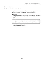
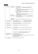
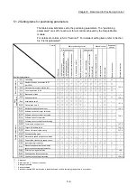
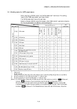
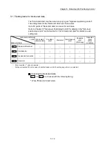
5.1.3 Setting items for OPR parameters
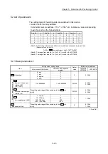
When carrying out "OPR control", the "OPR parameters" must be set. The setting
items for the "OPR parameters" are shown below.
The "OPR parameters" are set for each axis.
Refer to Chapter 8 "OPR control" for details on the "OPR control", and refer to Section
5.2 "List of parameters" for details on each setting item.
OPR control
OPR parameters
Machine OPR control
Fast
OPR control
OP
R bas
ic
param
et
ers
Pr.43 OPR method
Near
-poi
nt
dog
m
et
hod
Count
m
et
hod 1)
Count
m
et
hod 2)
Dat
a s
et
m
et
hod
S
cal
e ori
gi
n s
ignal
det
ec
tion m
et
hod
Dri
ver OP
R
m
et
hod
–
Pr.44 OPR direction
(Note-1)
–
Pr.45 OP address
Pr.46 OPR speed
–
–
Pr.47 Creep speed
–
– –
Pr.48 OPR retry
R
R
R
–
–
–
–
OP
R det
ai
led param
et
er
s
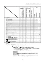
Pr.50
Setting for the movement amount after
near-point dog ON
–
– – –
–
Pr.51 OPR acceleration time selection
–
–
Pr.52 OPR deceleration time selection
–
–
Pr.53 OP shift amount
S S S –
S
– –
Pr.54 OPR torque limit value
–
–
Pr.55 Operation setting for incompletion of OPR
–
Pr.56 Speed designation during OP shift
S
S
S
–
S
–
–
Pr.57 Dwell time during OPR retry
R
R
R
–
–
–
–
: Always set
: Set as required
– : Setting not required (When the value is the default value or within the setting range, there is no problem.)
R : Set when using the "13.2.1 OPR retry function" ("–" when not set)
S : Set when using the "13.2.2 OP shift function" ("–" when not set)
(Note-1): The OPR operation follows the OPR direction set in the driver and does not refer to "
Pr.44
OPR direction
".
However, "
Pr.44
OPR direction
" must be set when using the backlash compensation function.
When the positioning is executed in the reverse direction against "
Pr.44
OPR direction
", the backlash
compensation is executed in the axis operation such as positioning after the driver OPR. Set the same
direction to "
Pr.44
OPR direction
" of the Simple Motion module and the last OPR direction of the driver.
Summary of Contents for MELSEC-L Series
Page 2: ......
Page 30: ...MEMO ...
Page 70: ...2 10 Chapter 2 System Configuration MEMO ...
Page 83: ...3 13 Chapter 3 Specifications and Functions MEMO ...
Page 103: ...3 33 Chapter 3 Specifications and Functions MEMO ...
Page 107: ...3 37 Chapter 3 Specifications and Functions MEMO ...
Page 111: ...3 41 Chapter 3 Specifications and Functions MEMO ...
Page 115: ...3 45 Chapter 3 Specifications and Functions MEMO ...
Page 140: ...4 22 Chapter 4 Installation Wiring and Maintenance of the Product MEMO ...
Page 253: ...5 113 Chapter 5 Data Used for Positioning Control MEMO ...
Page 342: ...5 202 Chapter 5 Data Used for Positioning Control MEMO ...
Page 438: ...7 20 Chapter 7 Memory Configuration and Data Process MEMO ...
Page 440: ...MEMO ...
Page 485: ...9 25 Chapter 9 Major Positioning Control MEMO ...
Page 594: ...9 134 Chapter 9 Major Positioning Control MEMO ...
Page 624: ...10 30 Chapter 10 High Level Positioning Control MEMO ...
Page 656: ...11 32 Chapter 11 Manual Control MEMO ...
Page 690: ...12 34 Chapter 12 Expansion Control MEMO ...
Page 798: ...13 108 Chapter 13 Control Sub Functions MEMO ...
Page 866: ...14 68 Chapter 14 Common Functions MEMO ...
Page 884: ...15 18 Chapter 15 Dedicated Instructions MEMO ...
Page 899: ...16 15 Chapter 16 Troubleshooting MEMO ...
Page 1036: ...Appendix 88 Appendices MEMO ...
Page 1039: ......


