


3 - 24
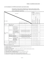
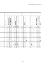
Chapter 3 Specifications and Functions
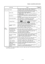
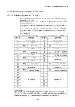
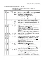
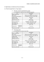
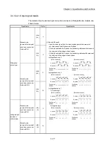
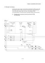
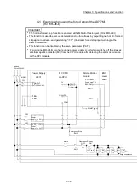
(3) Manual pulse generator/Incremental synchronous encoder input
(a) Specifications of manual pulse generator/incremental synchronous encoder
Item Specifications
Signal input form
(Note-1)
Phase A/Phase B (Magnification by 4/
Magnification by 2/Magnification by 1), PLS/SIGN
Differential-output
type
(26LS31 or
equivalent )
Maximum input pulse frequency
1Mpps (After magnification by 4, up to 4Mpps)
(Note-2)
Pulse width
1µs or more
Leading edge/trailing edge time
0.25µs or less
Phase difference
0.25µs or more
Rated input voltage
5.5 V DC or less
High-voltage
2.0 to 5.25 V DC
Low-voltage
0 to 0.8 V DC
Differential voltage
0.2V
Cable length
Up to 30m (98.43ft.)
Example of waveform
Phase A
Phase B
(Note): Duty ratio 50%
1 s or more
0.5 s or more
0.25 s or more
0.25 s
or less
0.5 s or more
0.25 s
or less
Voltage-output
type/Open-
collector type
(5 V DC)
Maximum input pulse frequency 200kpps (After magnification by 4, up to 800kpps)
(Note-2)
Pulse width
5µs or more
Leading edge/trailing edge time
1.2µs or less
Phase difference
1.2µs or more
Rated input voltage
5.5 V DC or less
High-voltage
3.0 to 5.25 V DC/2 mA or less
Low-voltage
0 to 1.0 V DC/5 mA or more
Cable length
Up to 10m (32.81ft.)
Example of waveform
Phase A
Phase B
(Note): Duty ratio 50%
1.2 s
or less
1.2 s or more
2.5 s or more
5 s or more
2.5 s or more
1.2 s
or less
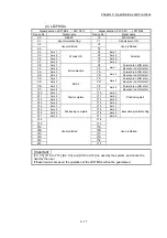
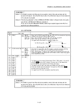
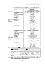
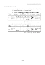
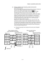
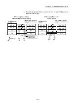
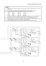
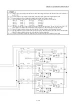
(Note-1): Set the signal input form in "
Pr.24
Manual pulse generator/Incremental synchronous encoder input selection".
Pr.24
Manual pulse generator/
Incremental synchronous encoder
input selection
Pr.22
Input signal logic selection
Positive logic
Negative logic
Forward run
Reverse run
Forward run
Reverse run
Phase A/Phase B
PLS/SIGN
HIGH
LOW
HIGH
LOW
(Note-2): Maximum input pulse frequency is magnified by 4, when "A-phase/B-phase Magnification by 4" is set in "
Pr.24
Manual pulse generator/Incremental synchronous encoder input selection".
Summary of Contents for MELSEC-L Series
Page 2: ......
Page 30: ...MEMO ...
Page 70: ...2 10 Chapter 2 System Configuration MEMO ...
Page 83: ...3 13 Chapter 3 Specifications and Functions MEMO ...
Page 103: ...3 33 Chapter 3 Specifications and Functions MEMO ...
Page 107: ...3 37 Chapter 3 Specifications and Functions MEMO ...
Page 111: ...3 41 Chapter 3 Specifications and Functions MEMO ...
Page 115: ...3 45 Chapter 3 Specifications and Functions MEMO ...
Page 140: ...4 22 Chapter 4 Installation Wiring and Maintenance of the Product MEMO ...
Page 253: ...5 113 Chapter 5 Data Used for Positioning Control MEMO ...
Page 342: ...5 202 Chapter 5 Data Used for Positioning Control MEMO ...
Page 438: ...7 20 Chapter 7 Memory Configuration and Data Process MEMO ...
Page 440: ...MEMO ...
Page 485: ...9 25 Chapter 9 Major Positioning Control MEMO ...
Page 594: ...9 134 Chapter 9 Major Positioning Control MEMO ...
Page 624: ...10 30 Chapter 10 High Level Positioning Control MEMO ...
Page 656: ...11 32 Chapter 11 Manual Control MEMO ...
Page 690: ...12 34 Chapter 12 Expansion Control MEMO ...
Page 798: ...13 108 Chapter 13 Control Sub Functions MEMO ...
Page 866: ...14 68 Chapter 14 Common Functions MEMO ...
Page 884: ...15 18 Chapter 15 Dedicated Instructions MEMO ...
Page 899: ...16 15 Chapter 16 Troubleshooting MEMO ...
Page 1036: ...Appendix 88 Appendices MEMO ...
Page 1039: ......


