

5 - 65
Chapter 5 Data Used for Positioning Control
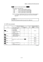
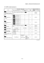
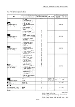
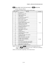
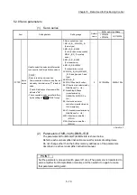
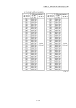
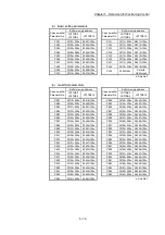
5.2.7 Expansion parameters
Item
Setting value, setting range
Default value
Buffer memory address
Value set with GX Works2
Value set with sequence
program
LD77MS2
LD77MS4
LD77MS16
Pr.91
Optional data monitor:
Data type setting 1
0 : No setting
1 : Effective load ratio
(Note-2)
2 : Regenerative load ratio
3 : Peak load ratio
4 : Load inertia moment ratio
(Note-2)
5 : Model loop gain
(Note-2)
6 : Main circuit bus voltage
(Note-2)
7 : Servo motor speed
(Note-2)
8 : Encoder multiple revolution
counter
9 : Module power consumption
10 : Instantaneous torque
(Note-2)
12 : Servo motor thermistor
temperature
13 : Disturbance torque
(Note-2)
14 : Overload alarm margin
15 : Error excessive alarm
margin
16 : Settling time
17 : Overshoot amount
18 : Internal temperature of
encoder
20 : Position feedback
(Note-1)
21 : Encoder position within one
revolution
(Note-1)
22 : Selected droop pulse
(Note-1)
23 : Module integral power
consumption
(Note-1)
24 : Load-side encoder
information 1
(Note-1)
25 : Load-side encoder
information 2
(Note-1)
26 : Z-phase counter
(Note-1)
27 : Servo motor side/load-side
position deviation
(Note-1)
28 : Servo motor side/load-side
speed deviation
(Note-1)
29 : External encoder counter
value
(Note-1)
30 : Module power consumption
(2 words)
(Note-1)
0
1
2
3
4
5
6
7
8
9
10
12
13
14
15
16
17
18
20
21
22
23
24
25
26
27
28
29
30
0 100+150n
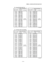
Pr.92
Optional data monitor:
Data type setting 2
0 101+150n
Pr.93
Optional data monitor:
Data type setting 3
0 102+150n
Pr.94
Optional data monitor:
Data type setting 4
0 103+150n
Pr.96
Operation cycle setting
0: 0.88ms
1: 1.77ms
0
1
LD77MS2 : 0
LD77MS4 : 0
LD77MS16: 1
147
(Note-3)
105
(Note-3)
Pr.97
SSCNET setting
0: SSCNET
1: SSCNET /H
0
1
1
106
(Note-3)
Pr.114
External command signal
compensation valid/invalid
setting
0: Invalid
1: Valid
0
1
0
114
(Note-3)
n: Axis No. -1
(Note-1): Used point: 2 words
(Note-2): The name differs depending on the connected
device.
(Note-3): Only the value specified against the axis 1 is valid.
Summary of Contents for MELSEC-L Series
Page 2: ......
Page 30: ...MEMO ...
Page 70: ...2 10 Chapter 2 System Configuration MEMO ...
Page 83: ...3 13 Chapter 3 Specifications and Functions MEMO ...
Page 103: ...3 33 Chapter 3 Specifications and Functions MEMO ...
Page 107: ...3 37 Chapter 3 Specifications and Functions MEMO ...
Page 111: ...3 41 Chapter 3 Specifications and Functions MEMO ...
Page 115: ...3 45 Chapter 3 Specifications and Functions MEMO ...
Page 140: ...4 22 Chapter 4 Installation Wiring and Maintenance of the Product MEMO ...
Page 253: ...5 113 Chapter 5 Data Used for Positioning Control MEMO ...
Page 342: ...5 202 Chapter 5 Data Used for Positioning Control MEMO ...
Page 438: ...7 20 Chapter 7 Memory Configuration and Data Process MEMO ...
Page 440: ...MEMO ...
Page 485: ...9 25 Chapter 9 Major Positioning Control MEMO ...
Page 594: ...9 134 Chapter 9 Major Positioning Control MEMO ...
Page 624: ...10 30 Chapter 10 High Level Positioning Control MEMO ...
Page 656: ...11 32 Chapter 11 Manual Control MEMO ...
Page 690: ...12 34 Chapter 12 Expansion Control MEMO ...
Page 798: ...13 108 Chapter 13 Control Sub Functions MEMO ...
Page 866: ...14 68 Chapter 14 Common Functions MEMO ...
Page 884: ...15 18 Chapter 15 Dedicated Instructions MEMO ...
Page 899: ...16 15 Chapter 16 Troubleshooting MEMO ...
Page 1036: ...Appendix 88 Appendices MEMO ...
Page 1039: ......


