

12 - 22
Chapter 12 Expansion Control
[3] Speed control mode
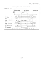
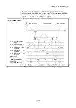
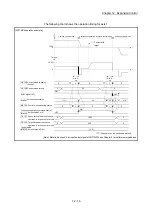
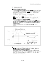
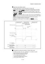
Operation for speed control mode
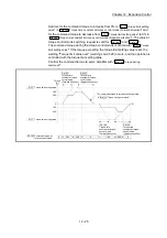
The speed control is executed at the speed set in "
Cd.140
Command speed at speed
control mode
" in the speed control mode. Set a positive value for forward rotation
and a negative value for reverse rotation. "
Cd.140
" can be changed any time
during the speed control mode.
Acceleration/deceleration is performed based on a trapezoidal
acceleration/deceleration processing. Set acceleration/deceleration time toward
"
Pr.8
Speed limit value
" in "
Cd.141
Acceleration time at speed control mode
" and
"
Cd.142
Deceleration time at speed control mode
". The value at speed control mode
switching request is valid for "
Cd.141
" and "
Cd.142
".
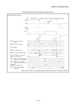
The command speed during the speed control mode is limited with "
Pr.8
Speed
limit value
". If the speed exceeding the speed limit value is set, the warning "Speed
limit value over" (warning code: 501) occurs, and the operation is controlled with
the speed limit value.
Confirm the command speed to servo amplifier with "
Md.122
Speed during
command
".
Cd.142
Deceleration time at
speed control mode
0
t
V
0
20000
30000
-10000
-20000
0
0
Pr.8 Speed limit value
30000
20000
-10000
-20000
Pr.8 Speed limit value
Md.122
The command speed to servo amplifier is stored
in " Speed during command".
Cd.141
Acceleration time at
speed control mode
Cd.140 Command speed at
speed control mode
Cd.141
Acceleration time at
speed control mode
Cd.142
Deceleration time at
speed control mode
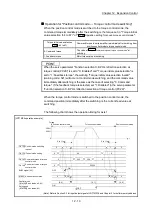
Current feed value during speed control mode
"
Md.20
Current feed value
", "
Md.21
Machine feed value
" and "
Md.101
Real current
value
" are updated even in the speed control mode.
If the current feed value exceeds the software stroke limit, the error "Software
stroke limit +" (error code: 507) or "Software stroke limit -" (error code: 508) occurs
and the operation switches to the position control mode. Invalidate the software
stroke limit to execute one-way feed.
Summary of Contents for MELSEC-L Series
Page 2: ......
Page 30: ...MEMO ...
Page 70: ...2 10 Chapter 2 System Configuration MEMO ...
Page 83: ...3 13 Chapter 3 Specifications and Functions MEMO ...
Page 103: ...3 33 Chapter 3 Specifications and Functions MEMO ...
Page 107: ...3 37 Chapter 3 Specifications and Functions MEMO ...
Page 111: ...3 41 Chapter 3 Specifications and Functions MEMO ...
Page 115: ...3 45 Chapter 3 Specifications and Functions MEMO ...
Page 140: ...4 22 Chapter 4 Installation Wiring and Maintenance of the Product MEMO ...
Page 253: ...5 113 Chapter 5 Data Used for Positioning Control MEMO ...
Page 342: ...5 202 Chapter 5 Data Used for Positioning Control MEMO ...
Page 438: ...7 20 Chapter 7 Memory Configuration and Data Process MEMO ...
Page 440: ...MEMO ...
Page 485: ...9 25 Chapter 9 Major Positioning Control MEMO ...
Page 594: ...9 134 Chapter 9 Major Positioning Control MEMO ...
Page 624: ...10 30 Chapter 10 High Level Positioning Control MEMO ...
Page 656: ...11 32 Chapter 11 Manual Control MEMO ...
Page 690: ...12 34 Chapter 12 Expansion Control MEMO ...
Page 798: ...13 108 Chapter 13 Control Sub Functions MEMO ...
Page 866: ...14 68 Chapter 14 Common Functions MEMO ...
Page 884: ...15 18 Chapter 15 Dedicated Instructions MEMO ...
Page 899: ...16 15 Chapter 16 Troubleshooting MEMO ...
Page 1036: ...Appendix 88 Appendices MEMO ...
Page 1039: ......


