


13 - 39
Chapter 13 Control Sub Functions
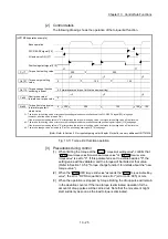
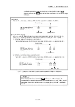
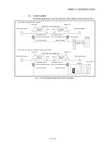
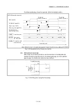
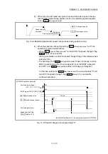
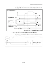
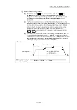
The following drawing shows the operation of the forced stop function.
[LD77MS4 operation example]
Each operation
PLC READY signal[Y0]
All axis servo ON[Y1]
Positioning start signal[Y10]
Forced stop input
(Input voltage of EMI)
Md.50
Forced stop input
1
0
Forced stop
causes occurrence
Pr.82
Forced stop valid/
invalid selection
0
Forced stop valid
Md.108
Servo status
(b1: Servo ON)
ON
0
1
OFF
1
ON
ON
OFF
Forced stop
causes occurrence
(Note): Refer to Section 3.3 for input/output signal and Chapter 5 for buffer memory address of LD77MS16.
Fig. 13.18 Operation for the forced stop function
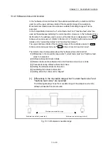
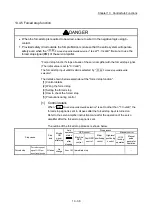
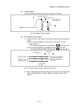
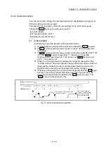
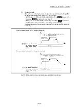
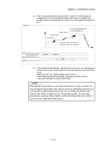
[2] Wiring the forced stop
When using the forced stop function, wire the terminals of the Simple Motion
module forced stop input as shown in the following drawing. As for the 24VDC
power supply, the direction of current can be switched.
Simple Motion module
EMI
EMI.COM
24VDC
Fig. 13.19 Wiring when using the forced stop
Summary of Contents for MELSEC-L Series
Page 2: ......
Page 30: ...MEMO ...
Page 70: ...2 10 Chapter 2 System Configuration MEMO ...
Page 83: ...3 13 Chapter 3 Specifications and Functions MEMO ...
Page 103: ...3 33 Chapter 3 Specifications and Functions MEMO ...
Page 107: ...3 37 Chapter 3 Specifications and Functions MEMO ...
Page 111: ...3 41 Chapter 3 Specifications and Functions MEMO ...
Page 115: ...3 45 Chapter 3 Specifications and Functions MEMO ...
Page 140: ...4 22 Chapter 4 Installation Wiring and Maintenance of the Product MEMO ...
Page 253: ...5 113 Chapter 5 Data Used for Positioning Control MEMO ...
Page 342: ...5 202 Chapter 5 Data Used for Positioning Control MEMO ...
Page 438: ...7 20 Chapter 7 Memory Configuration and Data Process MEMO ...
Page 440: ...MEMO ...
Page 485: ...9 25 Chapter 9 Major Positioning Control MEMO ...
Page 594: ...9 134 Chapter 9 Major Positioning Control MEMO ...
Page 624: ...10 30 Chapter 10 High Level Positioning Control MEMO ...
Page 656: ...11 32 Chapter 11 Manual Control MEMO ...
Page 690: ...12 34 Chapter 12 Expansion Control MEMO ...
Page 798: ...13 108 Chapter 13 Control Sub Functions MEMO ...
Page 866: ...14 68 Chapter 14 Common Functions MEMO ...
Page 884: ...15 18 Chapter 15 Dedicated Instructions MEMO ...
Page 899: ...16 15 Chapter 16 Troubleshooting MEMO ...
Page 1036: ...Appendix 88 Appendices MEMO ...
Page 1039: ......


