

16 - 16
Chapter 16 Troubleshooting
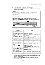
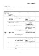
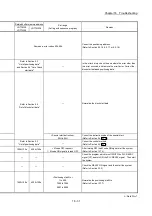
16.5 List of errors
The following table shows the error details and remedies to be taken when an error
occurs.
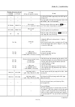
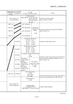
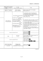
16.5.1 LD77MS detection error
Classification
of errors
Error
code
Error name
Error
Operation status at error occurrence
— 000
(Normal
status)
—
—
Fatal errors
001 Faults
Hardware is faulty.
The system stops.
002 Internal circuit fault
Common
errors
101
PLC READY OFF
during operation
The PLC READY signal [Y0] is turned OFF
during operation.
The system stops with the setting
(deceleration stop/sudden stop) of the
detailed parameter 2 Sudden stop selection
(stop group 2).
(Note that the deceleration stop only occurs
during the manual pulse generator operation.)
102
Servo READY signal
OFF during operation
The servo READY signal is turned OFF
during operation.
During operation: The system stops
immediately.
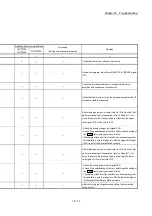
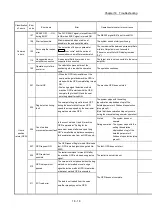
103
Test mode faults during
operation
The personal computer cannot
communicate with the CPU module.
The system stops with the setting
(deceleration stop/sudden stop) of the
detailed parameter 2 Sudden stop selection
(stop group 2).
(Note that the deceleration stop only occurs
during the manual pulse generator operation.)
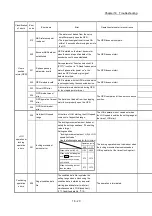
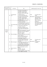
104
Hardware stroke limit
(+)
The hardware stroke limit (upper limit
signal FLS) is turned OFF during operation.
The system stops with the setting
(deceleration stop/sudden stop) of the
detailed parameter 2 Sudden stop selection
(stop group 1).
(Note that the deceleration stop only occurs
during the manual pulse generator operation.)
Start is requested when the hardware
stroke limit (upper limit signal FLS) is
turned OFF.
The system does not start.
105
Hardware stroke limit
(–)
The hardware stroke limit (lower limit signal
RLS) is turned OFF during operation.
The system stops with the setting
(deceleration stop/sudden stop) of the
detailed parameter 2 Sudden stop selection
(stop group 1).
(Note that the deceleration stop only occurs
during the manual pulse generator operation.)
Start is requested when the hardware
stroke limit (lower limit signal RLS) is
turned OFF.
The system does not start.
106 Stop signal ON at start
Start is requested when a stop signal is
turned ON.
The system does not start.
Summary of Contents for MELSEC-L Series
Page 2: ......
Page 30: ...MEMO ...
Page 70: ...2 10 Chapter 2 System Configuration MEMO ...
Page 83: ...3 13 Chapter 3 Specifications and Functions MEMO ...
Page 103: ...3 33 Chapter 3 Specifications and Functions MEMO ...
Page 107: ...3 37 Chapter 3 Specifications and Functions MEMO ...
Page 111: ...3 41 Chapter 3 Specifications and Functions MEMO ...
Page 115: ...3 45 Chapter 3 Specifications and Functions MEMO ...
Page 140: ...4 22 Chapter 4 Installation Wiring and Maintenance of the Product MEMO ...
Page 253: ...5 113 Chapter 5 Data Used for Positioning Control MEMO ...
Page 342: ...5 202 Chapter 5 Data Used for Positioning Control MEMO ...
Page 438: ...7 20 Chapter 7 Memory Configuration and Data Process MEMO ...
Page 440: ...MEMO ...
Page 485: ...9 25 Chapter 9 Major Positioning Control MEMO ...
Page 594: ...9 134 Chapter 9 Major Positioning Control MEMO ...
Page 624: ...10 30 Chapter 10 High Level Positioning Control MEMO ...
Page 656: ...11 32 Chapter 11 Manual Control MEMO ...
Page 690: ...12 34 Chapter 12 Expansion Control MEMO ...
Page 798: ...13 108 Chapter 13 Control Sub Functions MEMO ...
Page 866: ...14 68 Chapter 14 Common Functions MEMO ...
Page 884: ...15 18 Chapter 15 Dedicated Instructions MEMO ...
Page 899: ...16 15 Chapter 16 Troubleshooting MEMO ...
Page 1036: ...Appendix 88 Appendices MEMO ...
Page 1039: ......


