
1 - 29
Chapter 1 Product Outline
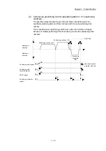
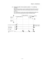
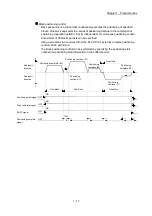
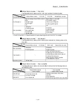
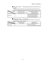
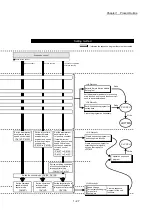
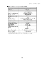
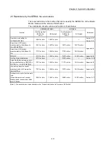
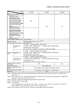
Stop cause
Stop
axis
M code
ON signal
after stop
Axis
operation
status
after
stopping
(
Md.26
)
Stop process
OPR control
Major
positioning
control
High-level
positioning
control
Manual control
Machine
OPR
control
Fast
OPR
control
JOG/
Inching
operation
Manual
pulse
generator
operation
Relatively safe
stop
(Stop group 3)
Axis error
detection
(Error other
than stop
group 1 or 2)
(Note-1)
Each
axis
No
change
Error
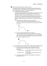
Deceleration stop/sudden stop
(Select with "
Pr.39
Stop group 3 sudden stop
selection
".)
Deceleration
stop
Intentional stop
(Stop group 3)
"Axis stop
signal" ON
from PLC
CPU
Each
axis
No
change
Stopped
(Standby)
"Stop" input
from
GX Works2
(Note-1): If an error occurs in a positioning data due to an invalid setting value, when the continuous positioning control uses multiple
positioning data successively, it automatically decelerates at the previous positioning data. It does not stop suddenly even the
setting value is sudden stop in stop group 3. If any of the following error occurs, the operation is performed up to the positioning
data immediately before the positioning data where an error occurred, and then stops immediately.
• No command speed (Error code: 503)
• Outside linear movement amount range (Error code: 504)
• Large arc error deviation (Error code: 506)
• Software stroke limit + (Error code: 507)
• Software stroke limit - (Error code: 508)
• Sub point setting error (Error code: 525)
• End point setting error (Error code: 526)
• Center point setting error (Error code: 527)
• Outside radius range (Error code: 544)
• Illegal setting of ABS direction in unit of degree (Error code: 546)
(Note-2): The failure during the test mode occurs in the following case.
• When the communication cannot be executed between the personal computer and the PLC CPU
REMARK
Provide the emergency stop circuits outside the servo system to prevent cases
where danger may result from abnormal operation of the overall system in the event
of an external power supply fault or servo system failure.
Summary of Contents for MELSEC-L Series
Page 2: ......
Page 30: ...MEMO ...
Page 70: ...2 10 Chapter 2 System Configuration MEMO ...
Page 83: ...3 13 Chapter 3 Specifications and Functions MEMO ...
Page 103: ...3 33 Chapter 3 Specifications and Functions MEMO ...
Page 107: ...3 37 Chapter 3 Specifications and Functions MEMO ...
Page 111: ...3 41 Chapter 3 Specifications and Functions MEMO ...
Page 115: ...3 45 Chapter 3 Specifications and Functions MEMO ...
Page 140: ...4 22 Chapter 4 Installation Wiring and Maintenance of the Product MEMO ...
Page 253: ...5 113 Chapter 5 Data Used for Positioning Control MEMO ...
Page 342: ...5 202 Chapter 5 Data Used for Positioning Control MEMO ...
Page 438: ...7 20 Chapter 7 Memory Configuration and Data Process MEMO ...
Page 440: ...MEMO ...
Page 485: ...9 25 Chapter 9 Major Positioning Control MEMO ...
Page 594: ...9 134 Chapter 9 Major Positioning Control MEMO ...
Page 624: ...10 30 Chapter 10 High Level Positioning Control MEMO ...
Page 656: ...11 32 Chapter 11 Manual Control MEMO ...
Page 690: ...12 34 Chapter 12 Expansion Control MEMO ...
Page 798: ...13 108 Chapter 13 Control Sub Functions MEMO ...
Page 866: ...14 68 Chapter 14 Common Functions MEMO ...
Page 884: ...15 18 Chapter 15 Dedicated Instructions MEMO ...
Page 899: ...16 15 Chapter 16 Troubleshooting MEMO ...
Page 1036: ...Appendix 88 Appendices MEMO ...
Page 1039: ......


