Chapter 4: Connecting External Equipment (Optional)
64
c.
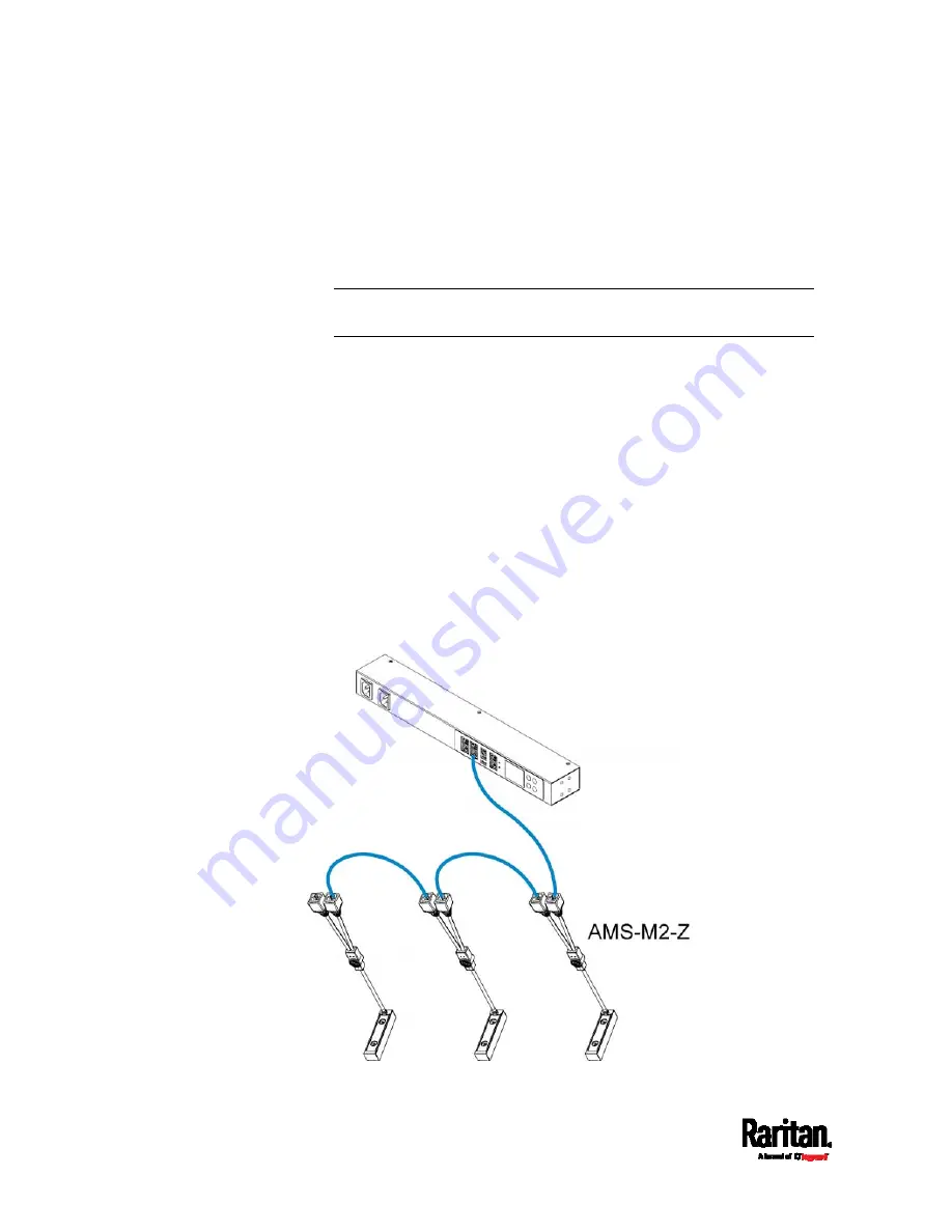
Connect the other end of the cable to the RJ-45 connector
labeled "Input" on the secondary composite asset strip.
d.
Repeat the same steps to connect more composite asset strips.
See
Daisy-Chain Limitations of Composite Asset Strips
(on
page 65) for the maximum number of composite asset strips
supported per chain.
Note: Different types of composite asset strips can be mixed in a
chain.
2.
Connect the composite asset strip(s) to the SRC device via a standard
network patch cable (CAT5e or higher).
a.
Connect one end of the cable to the RJ-45 port labeled "Input" on
the composite asset strip.
For a composite asset strip chain, connect the cable to the
"Input" port of the first asset strip.
b.
Connect the other end of the cable to the FEATURE port on the
SRC device.
3.
Affix an asset tag to the IT device. Then connect this asset tag to the
composite asset strip by plugging the tag connector into the tag port
on the composite asset strip. For details, see
Connecting Regular
Asset Strips to SRC
(on page 58).
4.
(Optional) For a chain, it is highly recommended using the cable ties
to help hold the weight of all connecting cables.
Summary of Contents for Raritan SRC-0100
Page 114: ...Chapter 6 Using the Web Interface 102...
Page 291: ...Chapter 6 Using the Web Interface 279...
Page 301: ...Chapter 6 Using the Web Interface 289 6 Click Create to finish the creation...
Page 311: ...Chapter 6 Using the Web Interface 299...
Page 312: ...Chapter 6 Using the Web Interface 300 Continued...
Page 625: ...Appendix H RADIUS Configuration Illustration 613 Note If your SRC uses PAP then select PAP...
Page 630: ...Appendix H RADIUS Configuration Illustration 618 14 The new attribute is added Click OK...
Page 631: ...Appendix H RADIUS Configuration Illustration 619 15 Click Next to continue...


