GENERAL INFORMATION
Repair procedure
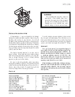
1. Most repair operations begin with an overview illustration. It identifies the components, shows how the parts fit
together and describes visual part inspection. However, only removal/installation procedures that need to be
performed methodically have written instructions.
2. Expendable parts, tightening torques and symbols for oil, grease, and sealant are shown in the overview
illustration. In addition, symbols indicating parts requiring the use of special service tools are also shown.
3. Procedure steps are numbered and the part that is the main point of that procedure is shown in the illustration
with the corresponding number. Occasionally, there are important points or additional information concerning
a procedure. Refer to this information when servicing the related part.
“Removal/Installation”
Portion
“Inspection After
Installation” Portion
SHOWS SERVICE
ITEM (S)
/
LOW ER TR A IU N G U N K . UPPER TRAILING LINK REMOVAL/INSTALLATION
1. J a c k up th e re a r o f th e v e h icle a nd su p p o rt it with sa fe ty stands.
2. Remove the undercover. (Refer to UNDERCOVER REMOVAL.) (Refer to UNDERCOVER INSTALLATION.)
3. Remove in the order indicated in the table.
4. Install in the reverse order of removal.
Indicates reievant
references that need to be
follow ed during installation.
5. Inspect the rear wheel alignment and adjust it if necessary.
Install the parts
by performing
steps 1—3 In
reverse order
SHOWS PROCEDURE ORDER
FOR SERVICE
SHOWS TIGHTENING
TORQUE
SPECIFICATIONS
SHOWS SPECIAL
SERVICE TOOL (SST)
FOR SERVICE OPERATION
SHOWS APPLICATION
POINTS OF GREASE, ETC.
SHOWS EXPENDABLE PARTS
»4-116 {«.5-11.®, «*-8«)
111-15« <«2.0-ie.0.17-115)
®D
SHOWS DETAILS
SHOWS TIGHTENING
TORQUE UNITS
SHOWS REFERRAL
NOTES FOR SERVICE
H-m { kgt-m , f r l b f }
1
S p lit p in
V
N u t
3 s h v to w e r tra ilin a lin k b a ll jo int
L y R e m o v a l N o te I
4
B olt
5
L o w e r tra ilin g lin k
6
D u s t b o o t (lo w e r tra ilin g link)
* r In s ta lla tio n N o te
7
S p lit pin
8
N u t
9
U p p e r trailin g lin k b a ll jo int
R e m o v a l N o te
1 0
N u t
11
U p p e r trailin g link
1 2
D u s t b o o t ( u p p e r t ra ilin g link)
R e m o v a l N o te
Low er Trailing Link Ball Joint, Upper Trailing Link
Ball Joint Removal Note
• Rem ove the ball Joint by using the SSTa.
49 T028 304
4 9 T 0 2 8 3 0 5
U P P E R T R A IU N G L INK
L O W E R T R A IU N G U N K
SHOWS SPECIAL
SERVICE TOOL (SST)
NO.
W*».|
11
r*u
SHOWS REFERRAL
NOTES FOR
SERVICE
W6UOOOWA1
0 0 -0 0 -3
Summary of Contents for MX-6 1998
Page 1: ......
Page 501: ...STARTING SYSTEM 3 If not as specified replace the starter interlock switch 01 19 3...
Page 803: ...MANUAL TRANSAXLE W 6 U 5 1 5 W A C 05 15 7...
Page 934: ...CONTROL SYSTEM CONTROL SYSTEM STRUCTURAL VIEW W6U740WA0 07 40 2...
Page 983: ...SERVICE TOOLS 08 60 SERVICE TOOLS 08 RESTRAINTS S S T 08 60 1 08 RESTRAINTS SST 08 60 1...


