


13
This chapter explains how to install your PX3TS and configure it for network
connectivity.
In This Chapter
Connecting Power and Equipment ..................................................................... 13
Connecting the PX3TS to Your Network ............................................................. 13
Configuring the PX3TS ........................................................................................ 16
Bulk Configuration Methods ............................................................................... 26
Cascading Multiple PX3TS Devices for Sharing Ethernet Connectivity ............... 27
Power-Sharing Restrictions and Connection ...................................................... 36
Connecting Power and Equipment
Your PX3TS may have fuses and/or circuit breakers. Verify that all are firmly
seated or set to ON before connecting power.
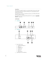
The PX3TS inlets are labeled INLET 1 (I1) and INLET 2 (I2). INLET 1 is the factory
default preferred inlet, and INLET 2 is the factory default alternate inlet.
Tip: You can switch preferred and alternate inlets if needed. See
Manual
Transfer
(on page 112).
To make power connections:
1.
Connect PX3TS inlets to branch circuits.
2.
Connect loads to PX3TS outlets.
3.
Apply power to branch circuits.
Connecting the PX3TS to Your Network
To remotely administer the PX3TS, you must connect the PX3TS to your local
area network (LAN). PX3TS can be connected to a wired or wireless network.
Note: If your PX3TS will work as a master device in the bridging mode, you must
make a wired connection. See
Cascading Multiple PX3TS Devices for Sharing
Ethernet Connectivity
(on page 27).
Ethernet port of PX3TS must be enabled for the described connection to work
properly, which has been enabled per default. See
Wired Network Settings
(on
page 311).
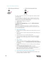
To make a wired connection:
1.
Connect a standard network patch cable to the Ethernet port on the
PX3TS.
2.
Connect the other end of the cable to your LAN.
Chapter 3
Initial Installation and Configuration
Содержание Raritan PX3TS
Страница 4: ......
Страница 6: ......
Страница 20: ......
Страница 52: ...Chapter 3 Initial Installation and Configuration 32 Number Device role Master device Slave 1 Slave 2 Slave 3...
Страница 80: ...Chapter 4 Connecting External Equipment Optional 60...
Страница 109: ...Chapter 5 PDU Linking 89...
Страница 117: ...Chapter 5 PDU Linking 97...
Страница 440: ...Chapter 7 Using the Web Interface 420 If wanted you can customize the subject and content of this email in this action...
Страница 441: ...Chapter 7 Using the Web Interface 421...
Страница 464: ...Chapter 7 Using the Web Interface 444...
Страница 465: ...Chapter 7 Using the Web Interface 445 Continued...
Страница 746: ...Appendix A Specifications 726...
Страница 823: ...Appendix I RADIUS Configuration Illustration 803 Note If your PX3TS uses PAP then select PAP...
Страница 824: ...Appendix I RADIUS Configuration Illustration 804 10 Select Standard to the left of the dialog and then click Add...
Страница 825: ...Appendix I RADIUS Configuration Illustration 805 11 Select Filter Id from the list of attributes and click Add...
Страница 828: ...Appendix I RADIUS Configuration Illustration 808 14 The new attribute is added Click OK...
Страница 829: ...Appendix I RADIUS Configuration Illustration 809 15 Click Next to continue...
Страница 860: ...Appendix J Additional PX3TS Information 840...
Страница 890: ...Appendix K Integration 870 3 Click OK...
Страница 900: ......


