


Chapter 3: Initial Installation and Configuration
37
•
All internal sensors become "unavailable", including sensors of inlets,
outlets, and OCPs.
Exception: Only active energy data remains available.
•
Communications with relay/meter boards are lost. Therefore, firmware
upgrade may fail due to this reason.
Available data or operations on the PDU that enters the power-sharing
mode:
•
Change software settings, such as customizing names, modifying network
settings, configuring thresholds, and so on.
Note: Outlet switching is not available because all outlets lose power.
•
Monitor the status of connected Raritan environmental sensor packages,
or configure/control their settings.
•
Operate the front panel display.
Events that occur when entering the power-sharing mode:
•
The 12V power supply sensor enters the fault state. See +12V Power
Supply Sensor.
Tip: You can set an event rule for sending a notification when this sensor
enters the fault state. See
Event Rules and Actions
(on page 375).
•
The above event is logged in the internal event log. See
Default Log
Messages
(on page 381).
To find whether a PX3TS has entered the power-sharing mode:
•
Check the state of its +12V power supply sensor.
Tip: For SNMP, the sensor type for this +12V power supply is i1smpsStatus (46).
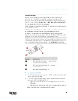
Making a Power-Sharing Connection
Make sure
BOTH
PX3TS devices comply with the configuration limitations when
establishing a power-sharing connection. See
Power-Sharing Configurations
and Restrictions
(on page 38).
The supported maximum power-sharing distance is 2 meters.
Make a power-sharing connection:
1.
Get a standard network patch cable (Cat5e/6), which can be up to 2
meters long.
▪
Do NOT use a crossover cable.
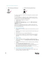
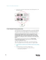
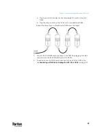
2.
Connect one end to a PX3TS device's EXPANSION port, and the other end
to another one's EXPANSION port.
▪
Note that the EXPANSION port location on your PX3TS may differ from
the following images.
Содержание Raritan PX3TS
Страница 4: ......
Страница 6: ......
Страница 20: ......
Страница 52: ...Chapter 3 Initial Installation and Configuration 32 Number Device role Master device Slave 1 Slave 2 Slave 3...
Страница 80: ...Chapter 4 Connecting External Equipment Optional 60...
Страница 109: ...Chapter 5 PDU Linking 89...
Страница 117: ...Chapter 5 PDU Linking 97...
Страница 440: ...Chapter 7 Using the Web Interface 420 If wanted you can customize the subject and content of this email in this action...
Страница 441: ...Chapter 7 Using the Web Interface 421...
Страница 464: ...Chapter 7 Using the Web Interface 444...
Страница 465: ...Chapter 7 Using the Web Interface 445 Continued...
Страница 746: ...Appendix A Specifications 726...
Страница 823: ...Appendix I RADIUS Configuration Illustration 803 Note If your PX3TS uses PAP then select PAP...
Страница 824: ...Appendix I RADIUS Configuration Illustration 804 10 Select Standard to the left of the dialog and then click Add...
Страница 825: ...Appendix I RADIUS Configuration Illustration 805 11 Select Filter Id from the list of attributes and click Add...
Страница 828: ...Appendix I RADIUS Configuration Illustration 808 14 The new attribute is added Click OK...
Страница 829: ...Appendix I RADIUS Configuration Illustration 809 15 Click Next to continue...
Страница 860: ...Appendix J Additional PX3TS Information 840...
Страница 890: ...Appendix K Integration 870 3 Click OK...
Страница 900: ......


