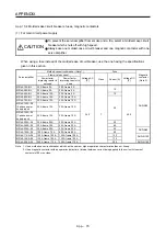
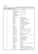
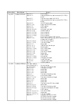
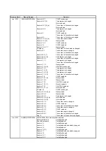
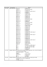

Revision Date
*Manual Number
Revision
Feb. 2013
SH(NA)030107ENG-E COMPLIANCE WITH
UL/CSA STANDARD
COMPLIANCE WITH KC
MARK
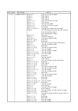
Section 1.1
Section 1.2
Section 1.2 (1)
Section 1.2 (2)
Section 1.2 (3)
Section 1.3
Section 1.4
Section 1.5
Section 1.6 (2)
Section 1.7.1 (1)
Section 1.7.1 (1) to (4)
Section 1.7.1 (5), (6)
Section 1.7.2
Section 1.8 (1) to (4)
Section 1.8 (5), (4)
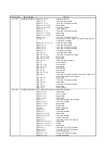
Chapter 2
Section 2.1 (1) (a), (b)
Section 2.4 (1) to (6)
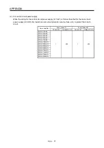
Chapter 3
Section 3.1
Section 3.1 (1) to (4)
Section 3.1 (5)
Section 3.2.1 (1)
Section 3.2.1 (2)
Section 3.2.2 (1)
Section 3.2.2 (2)
Section 3.2.3 (1)
Section 3.2.3 (2)
Section 3.3.1
Section 3.3.2
Section 3.3.2 (2)
Section 3.4
Section 3.5 (1) (a)
Section 3.5 (1) (b)
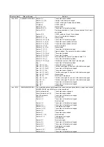
Section 3.6.1 (5)
Section 3.6.2 (1)
Section 3.6.3 (1), (3)
Section 3.6.4 (3) (a)
Section 3.6.5 (4) (a)
Section 3.6.6 (1)
Section 3.7.3
Section 3.9.1
Section 3.10.1 (1)
Section 3.10.2 (1) (b)
Section 4.1.2 (1) (b) 5)
Section 4.1.2 (1) (c)
Section 4.5.1
Section 4.5.2
Section 4.5.3 (1)
Section 4.5.3 (3)
Section 4.5.4
Section 4.5.6
Section 4.5.9 (2) (b)
Section 4.5.9 (3)
Section 4.5.9 (3) (a) d)
Section 4.5.9 (4)
Chapter 5
The reference is changed.
The reference is changed.
The sentences and table of combination are added.
POINT is added.
CN2L connector, Note 5 and 6 are added.
CN2L connector, Note 3 and 4 are added.
11 kW to 22 kW and Note 5 are added.
Note 3 is changed. Note 10 and 11 kW to 22 kW are added. A
part of specifications is added and changed.
POINT is added. The table of combination is changed.
Function item is added.
Table is changed and added.
Table item (17), (18), and Note are added. The diagram is
changed.
The diagram is changed.
11 kW to 22 kW are added.
The sentences are added.
CN2L connector and Note 4 are added.
11 kW to 22 kW are added.
Two items are added to CAUTION.
Note 1 and 2 are added.
Note 5 is added.
The diagram of CAUTION is changed. POINT is added.
CAUTION is added.
The connection diagram is changed. Note 11 is added.
Newly added.
The connection diagram is changed. Note 3 and 4 are
changed.
The connection diagram is changed.
The connection diagram is changed. Note 3 and 4 are
changed.
The connection diagram is changed.
The connection diagram is changed. Note 3 and 4 are
changed.
The connection diagram is changed.
The table is changed.
POINT is added.
Note is added.
Note 1, 2, and CN2L are added.
The content is added. The sentences are added.
The item is added.
The connection diagram is changed.
The connection diagram is changed.
The connection diagram is changed.
The connection diagram is changed.
The connection diagram is changed.
Note is added.
The content is added.
Note 4 and 5 are added. The connection diagram is changed.
The connection diagram is changed.
The content is changed.
Newly added.
4) is added.
The explanation is added.
The display content is added.
The display content is added.
The display content is added.
Note is added.
The display content is added.
The sentences are changed.
The sentences are changed.
The sentences are changed.
The sentences are changed.
CAUTION is added. POINT is added.
Summary of Contents for MR-J4-100A(-RJ)
Page 19: ...10 MEMO ...
Page 75: ...1 FUNCTIONS AND CONFIGURATION 1 56 MEMO ...
Page 83: ...2 INSTALLATION 2 8 MEMO ...
Page 159: ...3 SIGNALS AND WIRING 3 76 MEMO ...
Page 203: ...4 STARTUP 4 44 MEMO ...
Page 351: ...7 SPECIAL ADJUSTMENT FUNCTIONS 7 40 MEMO ...
Page 365: ...8 TROUBLESHOOTING 8 14 MEMO ...
Page 387: ...9 DIMENSIONS 9 22 MEMO ...
Page 403: ...10 CHARACTERISTICS 10 16 MEMO ...
Page 553: ...12 ABSOLUTE POSITION DETECTION SYSTEM 12 30 MEMO ...
Page 567: ...13 USING STO FUNCTION 13 14 MEMO ...
Page 607: ...14 COMMUNICATION FUNCTION MITSUBISHI ELECTRIC GENERAL PURPOSE AC SERVO PROTOCOL 14 40 MEMO ...
Page 639: ...15 USING A LINEAR SERVO MOTOR 15 32 MEMO ...
Page 767: ...18 MR J4 03A6 RJ SERVO AMPLIFIER 18 84 MEMO ...
Page 856: ...APPENDIX App 41 ...
Page 905: ...MEMO ...


