


1. FUNCTIONS AND CONFIGURATION
1 - 28
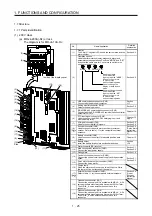
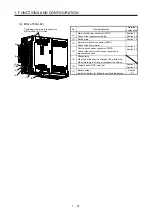
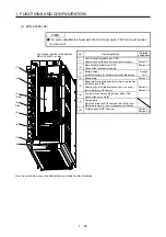
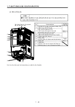
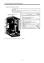
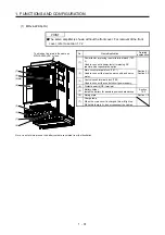
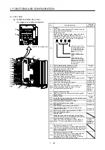
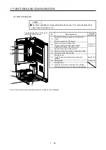
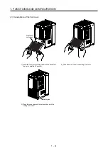
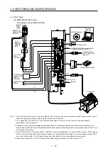
(c) MR-J4-500A(-RJ)
POINT
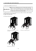
The servo amplifier is shown with the front cover open. The front cover cannot
be removed.
(1)
(3)
(2)
(Note)
(8)
(4)
Side
(5)
(6)
(7)
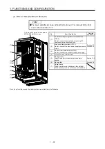
The broken line area is the same as
MR-J4-200A(-RJ) or less.
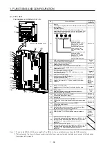
No. Name/Application
Detailed
explanation
(1)
Control circuit terminal block (TE2)
Used to connect the control circuit power supply.
Section 3.1
Section 3.3
(2)
Main circuit terminal block (TE1)
Connect the input power supply.
(3)
Battery holder
Install the battery for absolute position data backup.
Section
12.2
(4) Rating
plate
Section 1.6
(5)
Regenerative option/power factor improving reactor
terminal block (TE3)
Used to connect a regenerative option or a power
factor improving DC reactor.
Section 3.1
Section 3.3
(6)
Servo motor power supply terminal block (TE4)
Connect the servo motor.
(7)
Charge lamp
When the main circuit is charged, this will light up.
While this lamp is lit, do not reconnect the cables.
(8) Protective earth (PE) terminal
Section 3.1
Section 3.3
Note. Lines for slots around the battery holder are omitted from the illustration.
Summary of Contents for MR-J4-100A(-RJ)
Page 19: ...10 MEMO ...
Page 75: ...1 FUNCTIONS AND CONFIGURATION 1 56 MEMO ...
Page 83: ...2 INSTALLATION 2 8 MEMO ...
Page 159: ...3 SIGNALS AND WIRING 3 76 MEMO ...
Page 203: ...4 STARTUP 4 44 MEMO ...
Page 351: ...7 SPECIAL ADJUSTMENT FUNCTIONS 7 40 MEMO ...
Page 365: ...8 TROUBLESHOOTING 8 14 MEMO ...
Page 387: ...9 DIMENSIONS 9 22 MEMO ...
Page 403: ...10 CHARACTERISTICS 10 16 MEMO ...
Page 553: ...12 ABSOLUTE POSITION DETECTION SYSTEM 12 30 MEMO ...
Page 567: ...13 USING STO FUNCTION 13 14 MEMO ...
Page 607: ...14 COMMUNICATION FUNCTION MITSUBISHI ELECTRIC GENERAL PURPOSE AC SERVO PROTOCOL 14 40 MEMO ...
Page 639: ...15 USING A LINEAR SERVO MOTOR 15 32 MEMO ...
Page 767: ...18 MR J4 03A6 RJ SERVO AMPLIFIER 18 84 MEMO ...
Page 856: ...APPENDIX App 41 ...
Page 905: ...MEMO ...


