


18. MR-J4-03A6(-RJ) SERVO AMPLIFIER
18 - 18
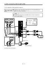
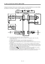
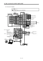
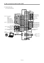
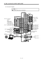
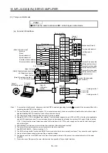
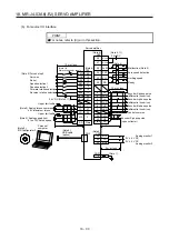
Configure the wirings so that the main circuit power supply is shut off and SON (Servo-on) is turned off after
deceleration to a stop due to an alarm occurring, enabled servo forced stop, etc.
ALM
DOCOM
CN1
(Note 3)
24 V DC (Note 7)
24 V DC (Note 7)
24
0
PM
Servo amplifier
U
V
W
CNP1
CNP1
Servo motor
U
V
W
M
Motor
Encoder
CN2
(Note 2)
Encoder cable
(Note 4)
Malfunction
RA1
OFF
RA2
ON
Emergency stop switch
CN1
Forced stop 2
Servo-on
(Note 3)
EM2
SON
DICOM
(Note 5)
Main circuit power supply
(Note 6)
Circuit
protector
24 V DC
(Note 1)
48 V DC
(Note 1)
48 V DC main circuit power supply
Circuit
protector
24 V DC
(Note 1)
24 V DC main circuit power supply
E
Malfunction
RA1
RA2
(Note 8)
RA2
24 V DC (Note 7)
(Note 9)
(Note 9)
Note 1. Use reinforced insulating type for 24 V DC and 48 V DC power supply.
2. For the encoder cable, use of the option cable is recommended. For selecting cables, refer to "Servo Motor
Instruction Manual (Vol. 3)".
3. This diagram shows sink I/O interface. For source I/O interface, refer to section 3.9.3.
4. For connecting servo motor power wires, refer to "Servo Motor Instruction Manual (Vol. 3)".
5. Configure a circuit to turn off EM2 when the main circuit power is turned off to prevent an unexpected restart of the
servo amplifier.
6. Connecting a servo motor of the wrong axis to U, V, W, or CN2 of the servo amplifier may cause a malfunction.
7. The illustration of the 24 V DC power supply is divided between input signal, output signal, and external emergency
stop circuit for convenience. However, they can be configured by one. For 24 V DC power for I/O signal, use power
other than 24 V DC power of servo amplifier control circuit power supply.
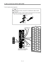
8. The noiseless grounding (
) terminals and E terminals are connected in the servo amplifier. Be sure to ground
from the noiseless grounding (
) terminal of CNP1 to the grounding terminal of the cabinet.
9. Circuit protectors are required for protection of power supplies, wires, servo amplifiers and others. When not using
a circuit protector, configure an external protective circuit such as a power supply with protection function.
Summary of Contents for MR-J4-100A(-RJ)
Page 19: ...10 MEMO ...
Page 75: ...1 FUNCTIONS AND CONFIGURATION 1 56 MEMO ...
Page 83: ...2 INSTALLATION 2 8 MEMO ...
Page 159: ...3 SIGNALS AND WIRING 3 76 MEMO ...
Page 203: ...4 STARTUP 4 44 MEMO ...
Page 351: ...7 SPECIAL ADJUSTMENT FUNCTIONS 7 40 MEMO ...
Page 365: ...8 TROUBLESHOOTING 8 14 MEMO ...
Page 387: ...9 DIMENSIONS 9 22 MEMO ...
Page 403: ...10 CHARACTERISTICS 10 16 MEMO ...
Page 553: ...12 ABSOLUTE POSITION DETECTION SYSTEM 12 30 MEMO ...
Page 567: ...13 USING STO FUNCTION 13 14 MEMO ...
Page 607: ...14 COMMUNICATION FUNCTION MITSUBISHI ELECTRIC GENERAL PURPOSE AC SERVO PROTOCOL 14 40 MEMO ...
Page 639: ...15 USING A LINEAR SERVO MOTOR 15 32 MEMO ...
Page 767: ...18 MR J4 03A6 RJ SERVO AMPLIFIER 18 84 MEMO ...
Page 856: ...APPENDIX App 41 ...
Page 905: ...MEMO ...


