
6. NORMAL GAIN ADJUSTMENT
6 - 12
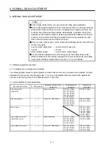
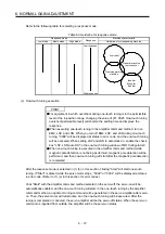
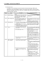
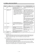
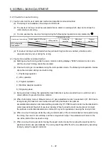
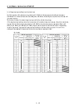
Refer to the following table for selecting a response mode.
Table 6.3 Guideline for response mode
Response mode
Response
Machine characteristic
Low mode
Basic mode
High mode
Guideline of corresponding machine
Low response
General machine
tool conveyor
Arm robot
Precision working
machine
Inserter
Mounter
Bonder
High response
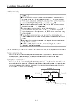
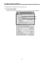
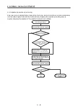
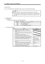
(c) One-touch tuning execution
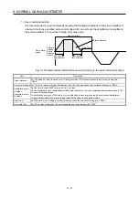
POINT
For equipment in which overshoot during one-touch tuning is in the permissible
level of the in-position range, changing the value of [Pr. PA25 One-touch tuning
overshoot permissible level] will shorten the settling time and improve the
response.
When executing one-touch tuning in the amplifier command method, turn on
EM2, LSP, and LSN. When you turn off EM2, LSP, and LSN during one-touch
tuning, "C008" will be displayed at status in error code, and the one-touch tuning
will be canceled. When setting LSP and LSN to automatic on, enable the check
box "LSP, LSN auto ON" in the one-touch tuning window of MR Configurator2.
When one-touch tuning is executed in the amplifier command method while
magnetic pole detection is not being performed, magnetic pole detection will be
performed, and then one-touch tuning will start after the magnetic pole detection
is completed.
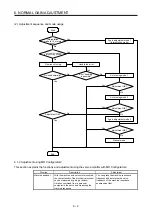
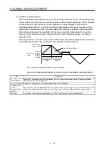
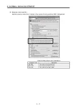
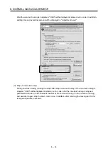
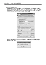
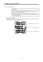
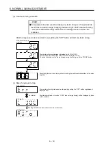
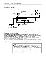
After the response mode is selected in (1) (b) in this section, clicking "Start" will start one-touch
tuning. If "Start" is clicked while the servo motor stops, "C002" or "C004" will be displayed at status
in error code. (Refer to (1) (e) in this section for error codes.)
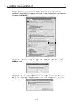
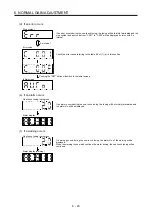
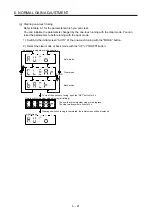
Click "Start" with the amplifier command method selected in the servo-off, the servo-on will be
automatically enabled, and the one-touch tuning will start. In the one-touch tuning by the amplifier
command method, an optimum tuning command will be generated in the servo amplifier after servo-
on. Then, the servo motor will reciprocate, and the one-touch tuning will be executed. After the
tuning is completed or canceled, the servo amplifier will be the servo-off status. When the servo-on
command is inputted from outside, the amplifier will be the servo-on status.
Summary of Contents for MR-J4-100A(-RJ)
Page 19: ...10 MEMO ...
Page 75: ...1 FUNCTIONS AND CONFIGURATION 1 56 MEMO ...
Page 83: ...2 INSTALLATION 2 8 MEMO ...
Page 159: ...3 SIGNALS AND WIRING 3 76 MEMO ...
Page 203: ...4 STARTUP 4 44 MEMO ...
Page 351: ...7 SPECIAL ADJUSTMENT FUNCTIONS 7 40 MEMO ...
Page 365: ...8 TROUBLESHOOTING 8 14 MEMO ...
Page 387: ...9 DIMENSIONS 9 22 MEMO ...
Page 403: ...10 CHARACTERISTICS 10 16 MEMO ...
Page 553: ...12 ABSOLUTE POSITION DETECTION SYSTEM 12 30 MEMO ...
Page 567: ...13 USING STO FUNCTION 13 14 MEMO ...
Page 607: ...14 COMMUNICATION FUNCTION MITSUBISHI ELECTRIC GENERAL PURPOSE AC SERVO PROTOCOL 14 40 MEMO ...
Page 639: ...15 USING A LINEAR SERVO MOTOR 15 32 MEMO ...
Page 767: ...18 MR J4 03A6 RJ SERVO AMPLIFIER 18 84 MEMO ...
Page 856: ...APPENDIX App 41 ...
Page 905: ...MEMO ...


