

3. SIGNALS AND WIRING
3 - 21
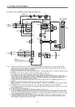
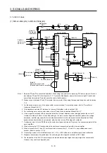
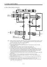
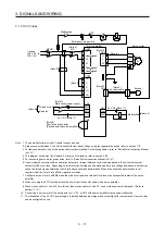
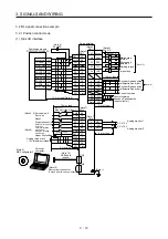
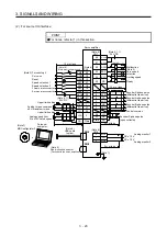
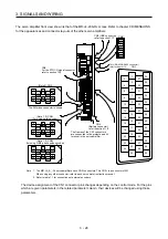
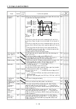
3.3 Explanation of power supply system
3.3.1 Signal explanations
POINT
For the layout of connector and terminal block, refer to chapter 9 DIMENSIONS.
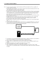
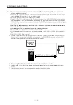
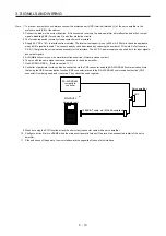
When using the MR-J4-_A-RJ servo amplifier with the DC power supply input,
refer to app. 13.
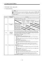
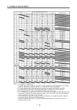
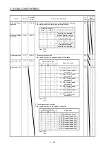
Symbol
Connection target
(application)
Description
L1/L2/L3
Main circuit power
supply
Supply the following power to L1, L2, and L3. For 1-phase 200 V AC to 240 V AC, connect the
power supply to L1 and L3. Leave L2 open.
Servo
amplifier
Power
MR-J4-10A
(-RJ) to
MR-J4-200A
(-RJ)
MR-J4-350A
(-RJ) to
MR-J4-22KA
(-RJ)
MR-J4-60A4
(-RJ) to
MR-J4-22KA4
(-RJ)
MR-J4-10A1 to
MR-J4-40A1
3-phase 200 V AC to
240 V AC, 50 Hz/60 Hz
L1/L2/L3
1-phase 200 V AC to
240 V AC, 50 Hz/60 Hz
L1/L3
3-phase 380 V AC to
480 V AC, 50 Hz/60 Hz
L1/L2/L3
1-phase 100 V AC to
120 V AC, 50 Hz/60 Hz
L1/L2
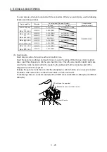
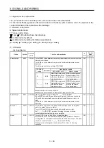
P3/P4
Power factor
improving
DC reactor
When not using the power factor improving DC reactor, connect P3 and P4 (factory-wired).
When using the power factor improving DC reactor, disconnect P3 and P4, and connect the
power factor improving DC reactor to P3 and P4. Additionally, the power factor improving DC
reactor cannot be used for the 100 V class servo amplifiers.
Refer to section 11.11 for details.
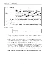
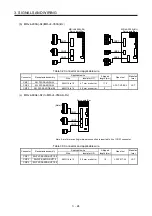
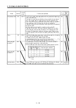
P+/C/D Regenerative
option
(1) 200 V class/100 V class
1) MR-J4-500A(-RJ) or less and MR-J4-40A1(-RJ) or less
When using a servo amplifier built-in regenerative resistor, connect P+ and D (factory-
wired).
When using a regenerative option, disconnect P+ and D, and connect the regenerative
option to P+ and C.
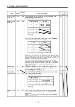
2) MR-J4-700A(-RJ) to MR-J4-22KA(-RJ)
MR-J4-700A(-RJ) to MR-J4-22KA(-RJ) do not have D.
When using a servo amplifier built-in regenerative resistor, connect P+ and C (factory-
wired).
When using a regenerative option, disconnect wires of P+ and C for the built-in
regenerative resistor. And then connect wires of the regenerative option to P+ and C.
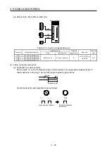
(2) 400 V class
1) MR-J4-350A4(-RJ) or less
When using a servo amplifier built-in regenerative resistor, connect P+ and D. (factory-
wired)
When using a regenerative option, disconnect P+ and D, and connect the regenerative
option to P+ and C.
2) MR-J4-500A4(-RJ) to MR-J4-22KA4(-RJ)
MR-J4-500A4(-RJ) to MR-J4-22KA4(-RJ) do not have D.
When using a servo amplifier built-in regenerative resistor, connect P+ and C. (factory-
wired)
When using a regenerative option, disconnect wires of P+ and C for the built-in
regenerative resistor. And then connect wires of the regenerative option to P+ and C.
Refer to section 11.2 for details.
Summary of Contents for MR-J4-100A(-RJ)
Page 19: ...10 MEMO ...
Page 75: ...1 FUNCTIONS AND CONFIGURATION 1 56 MEMO ...
Page 83: ...2 INSTALLATION 2 8 MEMO ...
Page 159: ...3 SIGNALS AND WIRING 3 76 MEMO ...
Page 203: ...4 STARTUP 4 44 MEMO ...
Page 351: ...7 SPECIAL ADJUSTMENT FUNCTIONS 7 40 MEMO ...
Page 365: ...8 TROUBLESHOOTING 8 14 MEMO ...
Page 387: ...9 DIMENSIONS 9 22 MEMO ...
Page 403: ...10 CHARACTERISTICS 10 16 MEMO ...
Page 553: ...12 ABSOLUTE POSITION DETECTION SYSTEM 12 30 MEMO ...
Page 567: ...13 USING STO FUNCTION 13 14 MEMO ...
Page 607: ...14 COMMUNICATION FUNCTION MITSUBISHI ELECTRIC GENERAL PURPOSE AC SERVO PROTOCOL 14 40 MEMO ...
Page 639: ...15 USING A LINEAR SERVO MOTOR 15 32 MEMO ...
Page 767: ...18 MR J4 03A6 RJ SERVO AMPLIFIER 18 84 MEMO ...
Page 856: ...APPENDIX App 41 ...
Page 905: ...MEMO ...


