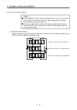
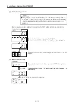
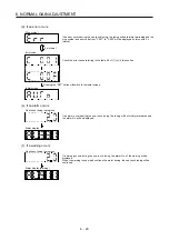
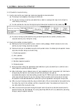
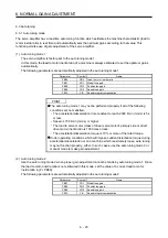
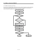
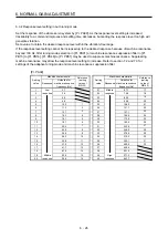

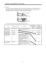
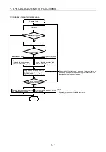

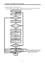

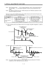

6. NORMAL GAIN ADJUSTMENT
6 - 32
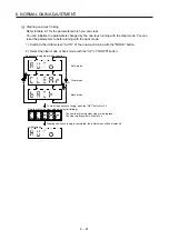
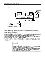
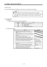
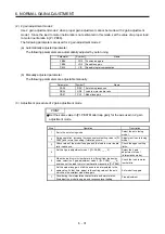
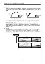
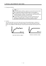
(4) Parameter adjustment
[Pr. PB07 Model loop gain]
This parameter determines the response level of the position control loop. Increasing the value improves
trackability to a position command, but a too high value will make overshoot liable to occur at settling.
Number of droop pulses is determined by the following expression.
Number of droop pulses [pulse] =
Model loop gain setting
Position command frequency [pulse/s]
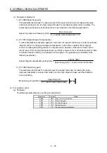
Position command frequency differs depending on the operation mode.
Position command frequency
=
Speed [r/min]
60
× Encoder resolution (number of pulses per servo motor revolution)
Summary of Contents for MR-J4-100A(-RJ)
Page 19: ...10 MEMO ...
Page 75: ...1 FUNCTIONS AND CONFIGURATION 1 56 MEMO ...
Page 83: ...2 INSTALLATION 2 8 MEMO ...
Page 159: ...3 SIGNALS AND WIRING 3 76 MEMO ...
Page 203: ...4 STARTUP 4 44 MEMO ...
Page 351: ...7 SPECIAL ADJUSTMENT FUNCTIONS 7 40 MEMO ...
Page 365: ...8 TROUBLESHOOTING 8 14 MEMO ...
Page 387: ...9 DIMENSIONS 9 22 MEMO ...
Page 403: ...10 CHARACTERISTICS 10 16 MEMO ...
Page 553: ...12 ABSOLUTE POSITION DETECTION SYSTEM 12 30 MEMO ...
Page 567: ...13 USING STO FUNCTION 13 14 MEMO ...
Page 607: ...14 COMMUNICATION FUNCTION MITSUBISHI ELECTRIC GENERAL PURPOSE AC SERVO PROTOCOL 14 40 MEMO ...
Page 639: ...15 USING A LINEAR SERVO MOTOR 15 32 MEMO ...
Page 767: ...18 MR J4 03A6 RJ SERVO AMPLIFIER 18 84 MEMO ...
Page 856: ...APPENDIX App 41 ...
Page 905: ...MEMO ...


