


3. SIGNALS AND WIRING
3 - 49
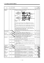
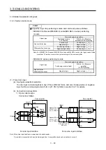
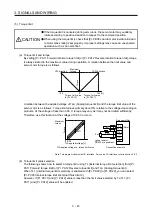
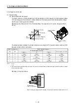
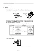
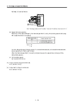
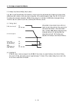
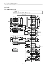
Normally, connect as follows.
Japan resistor
RRS10 or equivalent
SP2
DICOM
P15R
VLA
LG
SD
Servo amplifier
SP1
(Note)
2 k
Ω
2 k
Ω
24 V DC
Note. This diagram shows sink I/O interface. For source I/O interface, refer to section 3.9.3.
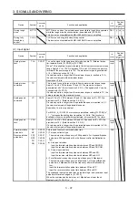
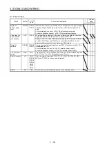
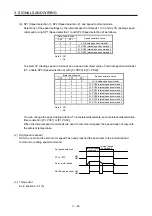
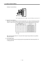
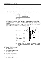
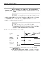
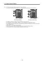
(b) Speed limit value selection
Select any of the speed settings by the internal speed limits 1 to 7 and by VLA (Analog speed limit)
using SP1 (Speed selection 1), SP2 (Speed selection 2), and SP3 (Speed selection 3) as follows.
(Note) Input device
Speed limit
SP3 SP2 SP1
0
0
0
VLA (Analog speed limit)
0
0
1
Pr. PC05 Internal speed limit 1
0
1
0
Pr. PC06 Internal speed limit 2
0
1
1
Pr. PC07 Internal speed limit 3
1
0
0
Pr. PC08 Internal speed limit 4
1
0
1
Pr. PC09 Internal speed limit 5
1
1
0
Pr. PC10 Internal speed limit 6
1
1
1
Pr. PC11 Internal speed limit 7
Note. 0: Off
1: On
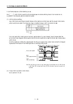
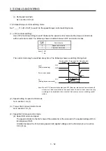
When the internal speed limits 1 to 7 are used to limit a speed, the speed does not vary with the
ambient temperature.
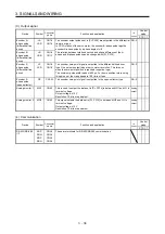
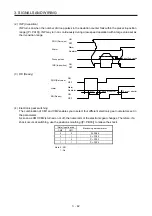
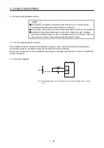
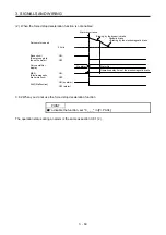
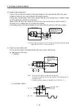
(c) VLC (Limiting speed)
VLC turns on when the servo motor speed reaches a speed limited with internal speed limits 1 to 7
or analog speed limit.
Summary of Contents for MR-J4-100A(-RJ)
Page 19: ...10 MEMO ...
Page 75: ...1 FUNCTIONS AND CONFIGURATION 1 56 MEMO ...
Page 83: ...2 INSTALLATION 2 8 MEMO ...
Page 159: ...3 SIGNALS AND WIRING 3 76 MEMO ...
Page 203: ...4 STARTUP 4 44 MEMO ...
Page 351: ...7 SPECIAL ADJUSTMENT FUNCTIONS 7 40 MEMO ...
Page 365: ...8 TROUBLESHOOTING 8 14 MEMO ...
Page 387: ...9 DIMENSIONS 9 22 MEMO ...
Page 403: ...10 CHARACTERISTICS 10 16 MEMO ...
Page 553: ...12 ABSOLUTE POSITION DETECTION SYSTEM 12 30 MEMO ...
Page 567: ...13 USING STO FUNCTION 13 14 MEMO ...
Page 607: ...14 COMMUNICATION FUNCTION MITSUBISHI ELECTRIC GENERAL PURPOSE AC SERVO PROTOCOL 14 40 MEMO ...
Page 639: ...15 USING A LINEAR SERVO MOTOR 15 32 MEMO ...
Page 767: ...18 MR J4 03A6 RJ SERVO AMPLIFIER 18 84 MEMO ...
Page 856: ...APPENDIX App 41 ...
Page 905: ...MEMO ...


