


3. SIGNALS AND WIRING
3 - 53
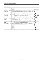
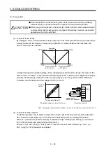
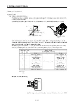
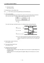
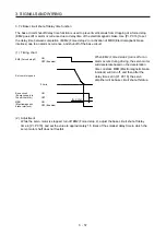
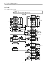
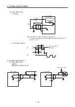
Normally, connect as follows.
Japan resistor
RRS10 or equivalent
DICOM
P15R
VLA
LG
SD
Servo amplifier
SP1
(Note)
2 k
Ω
2 k
Ω
24 V DC
Note. This diagram shows sink I/O interface. For source I/O interface, refer to section 3.9.3.
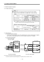
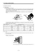
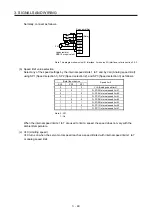
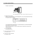
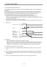
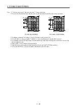
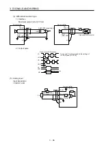
(b) Speed limit value selection
Select any of the speed settings by the internal speed limit 1 and by VLA (Analog speed limit) using
SP1 (Speed selection 1) as follows.
(Note) Input device
Speed command value
SP1
0
VLA (Analog speed limit)
1
Pr. PC05 Internal speed limit 1
Note. 0: Off
1: On
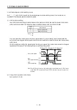
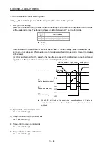
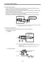
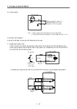
You can change the speed during rotation. To accelerate/decelerate, set acceleration/deceleration
time constant in [Pr. PC01] or [Pr. PC02].
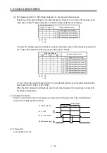
When the internal speed limit 1 is used to command a speed, the speed does not vary with the
ambient temperature.
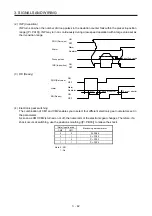
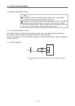
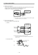
(c) VLC (Limiting speed)
As in section 3.6.3 (3) (c)
(5) Torque control in torque control mode
As in section 3.6.3 (1)
(6) Torque limit in torque control mode
As in section 3.6.3 (2)
Summary of Contents for MR-J4-100A(-RJ)
Page 19: ...10 MEMO ...
Page 75: ...1 FUNCTIONS AND CONFIGURATION 1 56 MEMO ...
Page 83: ...2 INSTALLATION 2 8 MEMO ...
Page 159: ...3 SIGNALS AND WIRING 3 76 MEMO ...
Page 203: ...4 STARTUP 4 44 MEMO ...
Page 351: ...7 SPECIAL ADJUSTMENT FUNCTIONS 7 40 MEMO ...
Page 365: ...8 TROUBLESHOOTING 8 14 MEMO ...
Page 387: ...9 DIMENSIONS 9 22 MEMO ...
Page 403: ...10 CHARACTERISTICS 10 16 MEMO ...
Page 553: ...12 ABSOLUTE POSITION DETECTION SYSTEM 12 30 MEMO ...
Page 567: ...13 USING STO FUNCTION 13 14 MEMO ...
Page 607: ...14 COMMUNICATION FUNCTION MITSUBISHI ELECTRIC GENERAL PURPOSE AC SERVO PROTOCOL 14 40 MEMO ...
Page 639: ...15 USING A LINEAR SERVO MOTOR 15 32 MEMO ...
Page 767: ...18 MR J4 03A6 RJ SERVO AMPLIFIER 18 84 MEMO ...
Page 856: ...APPENDIX App 41 ...
Page 905: ...MEMO ...


