


19. MR-D01 EXTENSION I/O UNIT
19 - 6
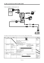
(1) For MR-J4-200A(4)-RJ or less and MR-J4-350A-RJ
(a) Installation of MR-D01
2)
2)
Guide pin
Guide hole
MR-D01
1)
1) Remove the covers of CN7 and CN9 connectors.
Make sure to store the removed cover.
2) Find the guide hole on the side of the servo amplifier. To
the guide hole, insert the MR-D01's guide pins.
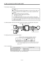
Knob
4)
3)
3) Push the four corners of the side of MR-D01 simultaneously
to the servo amplifier until the four knobs click so that the
CN7 connector is connected straight.
4) Tighten the unit with the enclosed installing screw (M4).
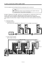
(b) Removal of MR-D01
1)
d)
c)
a)
2)
b)
1) Remove the installing screw.
2) Keep pushing the knobs ( a), b), c), d)) and pull out MR-D01
to the arrow direction. Avoid pulling out MR-D01 while it is
tightened with the installation screw.
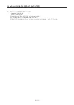
3)
3) After removing MR-D01, make sure to cap the CN7 and
CN9 connectors to avoid dust and dirt.
Summary of Contents for MR-J4-100A(-RJ)
Page 19: ...10 MEMO ...
Page 75: ...1 FUNCTIONS AND CONFIGURATION 1 56 MEMO ...
Page 83: ...2 INSTALLATION 2 8 MEMO ...
Page 159: ...3 SIGNALS AND WIRING 3 76 MEMO ...
Page 203: ...4 STARTUP 4 44 MEMO ...
Page 351: ...7 SPECIAL ADJUSTMENT FUNCTIONS 7 40 MEMO ...
Page 365: ...8 TROUBLESHOOTING 8 14 MEMO ...
Page 387: ...9 DIMENSIONS 9 22 MEMO ...
Page 403: ...10 CHARACTERISTICS 10 16 MEMO ...
Page 553: ...12 ABSOLUTE POSITION DETECTION SYSTEM 12 30 MEMO ...
Page 567: ...13 USING STO FUNCTION 13 14 MEMO ...
Page 607: ...14 COMMUNICATION FUNCTION MITSUBISHI ELECTRIC GENERAL PURPOSE AC SERVO PROTOCOL 14 40 MEMO ...
Page 639: ...15 USING A LINEAR SERVO MOTOR 15 32 MEMO ...
Page 767: ...18 MR J4 03A6 RJ SERVO AMPLIFIER 18 84 MEMO ...
Page 856: ...APPENDIX App 41 ...
Page 905: ...MEMO ...


