

12. ABSOLUTE POSITION DETECTION SYSTEM
12 - 10
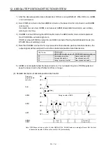
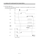
12.6 Absolute position data transfer protocol
POINT
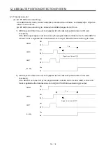
After switching on ABSM, turn on SON. When the ABS transfer mode is off,
turning on SON does not switch on the base circuit.
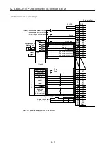
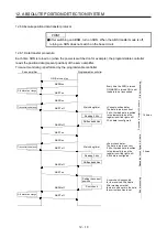
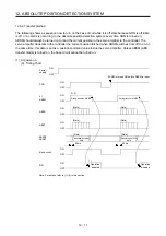
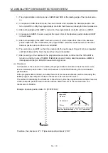
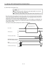
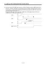
12.6.1 Data transfer procedure
Each time SON is turned on (when the power is switched on for example), the programmable controller
reads the position data (present position) of the servo amplifier.
Time-out monitoring is performed by the programmable controller.
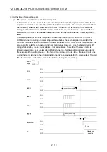
ON (Servo-on) on
Servo amplifier
Programmable controller
ABSM on
ABST on
ABSR on
ABST off
ABSR off
ABST on
ABSR on
ABST off
ABSR off
ABST on
ABSM off
DI0 allocation change
Transmission data set
Transmission data set
DI0 allocation change
Watch dog timer
Reading 2 bits
Shift and addition
Watch dog timer
Reading 2 bits
Shift and addition
Setting the current
position
Sum check
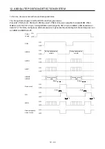
Every time the SON is turned
ON, ABSM is turned ON to set
the data to be transmitted.
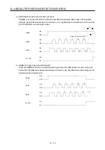
The data is read in units of
2 bits; the read data is written
to the lowest bits, and the
register is shifted right until
32-bit data is configured.
The data is read in units of
2 bits; the read data is written
to the lowest bits, and the
register is shifted right until
6-bit data is configured.
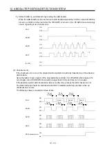
A sum check is executed
for the received 32-bit data.
After making sure that
there are no errors in the data,
the current position is set.
S
tar
t pr
o
ce
ssi
ng
Repe
ate
d
to con
figur
e 32-
bit
dat
a
Rep
e
at
ed
to
con
figure
6-b
it d
a
ta
E
nd p
roc
es
si
ng
16 times
3 times
«Current position data»
«Sum check data»
ABST off
Summary of Contents for MR-J4-100A(-RJ)
Page 19: ...10 MEMO ...
Page 75: ...1 FUNCTIONS AND CONFIGURATION 1 56 MEMO ...
Page 83: ...2 INSTALLATION 2 8 MEMO ...
Page 159: ...3 SIGNALS AND WIRING 3 76 MEMO ...
Page 203: ...4 STARTUP 4 44 MEMO ...
Page 351: ...7 SPECIAL ADJUSTMENT FUNCTIONS 7 40 MEMO ...
Page 365: ...8 TROUBLESHOOTING 8 14 MEMO ...
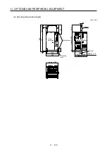
Page 387: ...9 DIMENSIONS 9 22 MEMO ...
Page 403: ...10 CHARACTERISTICS 10 16 MEMO ...
Page 553: ...12 ABSOLUTE POSITION DETECTION SYSTEM 12 30 MEMO ...
Page 567: ...13 USING STO FUNCTION 13 14 MEMO ...
Page 607: ...14 COMMUNICATION FUNCTION MITSUBISHI ELECTRIC GENERAL PURPOSE AC SERVO PROTOCOL 14 40 MEMO ...
Page 639: ...15 USING A LINEAR SERVO MOTOR 15 32 MEMO ...
Page 767: ...18 MR J4 03A6 RJ SERVO AMPLIFIER 18 84 MEMO ...
Page 856: ...APPENDIX App 41 ...
Page 905: ...MEMO ...


