
3. SIGNALS AND WIRING
3 - 70
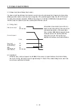
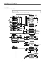
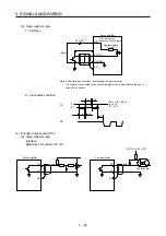
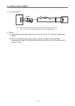
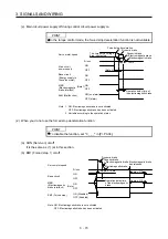
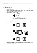
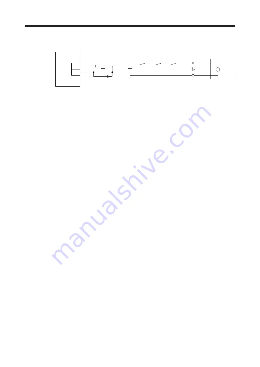
(1) Connection diagram
B2
B1
MBR
DOCOM
RA1
U
B
Servo motor
24 V DC
ALM
(Malfunction)
Servo amplifier
MBR
RA1
(Note 1)
(Note 2)
24 V DC
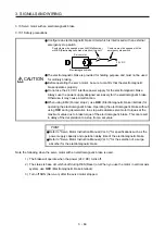
Note 1. Create the circuit in order to shut off by interlocking with the emergency stop switch.
2. Do not use the 24 V DC interface power supply for the electromagnetic brake.
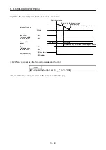
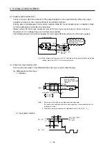
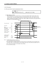
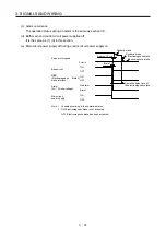
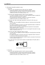
(2) Setting
(a) Enable MBR (Electromagnetic brake interlock) with [Pr. PD23] to [Pr. PD26], [Pr. PD28], and [Pr.
PD47].
(b) In [Pr. PC16 Electromagnetic brake sequence output], set a delay time (Tb) from MBR
(Electromagnetic brake interlock) off to base circuit shut-off at a servo-off as in the timing chart in
section 3.10.2 (1).
Summary of Contents for MR-J4-100A(-RJ)
Page 19: ...10 MEMO ...
Page 75: ...1 FUNCTIONS AND CONFIGURATION 1 56 MEMO ...
Page 83: ...2 INSTALLATION 2 8 MEMO ...
Page 159: ...3 SIGNALS AND WIRING 3 76 MEMO ...
Page 203: ...4 STARTUP 4 44 MEMO ...
Page 351: ...7 SPECIAL ADJUSTMENT FUNCTIONS 7 40 MEMO ...
Page 365: ...8 TROUBLESHOOTING 8 14 MEMO ...
Page 387: ...9 DIMENSIONS 9 22 MEMO ...
Page 403: ...10 CHARACTERISTICS 10 16 MEMO ...
Page 553: ...12 ABSOLUTE POSITION DETECTION SYSTEM 12 30 MEMO ...
Page 567: ...13 USING STO FUNCTION 13 14 MEMO ...
Page 607: ...14 COMMUNICATION FUNCTION MITSUBISHI ELECTRIC GENERAL PURPOSE AC SERVO PROTOCOL 14 40 MEMO ...
Page 639: ...15 USING A LINEAR SERVO MOTOR 15 32 MEMO ...
Page 767: ...18 MR J4 03A6 RJ SERVO AMPLIFIER 18 84 MEMO ...
Page 856: ...APPENDIX App 41 ...
Page 905: ...MEMO ...


