


12. ABSOLUTE POSITION DETECTION SYSTEM
12 - 29
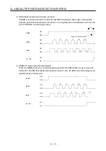
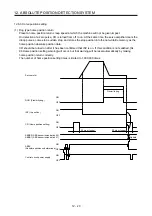
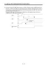
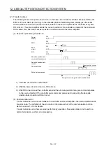
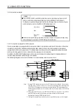
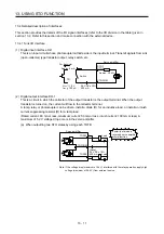
(d) At the time of forced stop reset
210 ms after the forced stop is deactivated, the base circuit turns on, and RD turns on further 5 ms
after that, turns on. Always get the current position data using RD as the trigger before the position
command is issued.
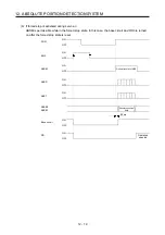
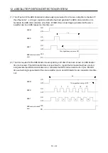
1) When power is switched on in a forced stop status
OFF
210 ms
ON
OFF
ON
OFF
ON
OFF
ON
OFF
ON
5 ms
During this period, get absolute position data.
Current position change
Power
supply
Base circuit
Pulse train command
Current position
Absolute position
data receive
Absolute position data
command transmission
SON
EM2
RD
Absolute position
data
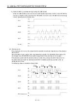
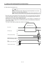
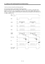
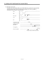
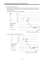
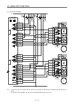
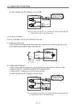
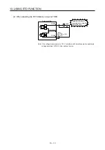
2) When a forced stop is activated during servo on
95 ms
ON
OFF
ON
OFF
ON
OFF
ON
OFF
5 ms
Pulse train command
Current position
Absolute position
data receive
Absolute position data
command transmission
Current position change
During this period, get absolute position data.
Base circuit
SON
EM2
RD
Absolute position
data
Summary of Contents for MR-J4-100A(-RJ)
Page 19: ...10 MEMO ...
Page 75: ...1 FUNCTIONS AND CONFIGURATION 1 56 MEMO ...
Page 83: ...2 INSTALLATION 2 8 MEMO ...
Page 159: ...3 SIGNALS AND WIRING 3 76 MEMO ...
Page 203: ...4 STARTUP 4 44 MEMO ...
Page 351: ...7 SPECIAL ADJUSTMENT FUNCTIONS 7 40 MEMO ...
Page 365: ...8 TROUBLESHOOTING 8 14 MEMO ...
Page 387: ...9 DIMENSIONS 9 22 MEMO ...
Page 403: ...10 CHARACTERISTICS 10 16 MEMO ...
Page 553: ...12 ABSOLUTE POSITION DETECTION SYSTEM 12 30 MEMO ...
Page 567: ...13 USING STO FUNCTION 13 14 MEMO ...
Page 607: ...14 COMMUNICATION FUNCTION MITSUBISHI ELECTRIC GENERAL PURPOSE AC SERVO PROTOCOL 14 40 MEMO ...
Page 639: ...15 USING A LINEAR SERVO MOTOR 15 32 MEMO ...
Page 767: ...18 MR J4 03A6 RJ SERVO AMPLIFIER 18 84 MEMO ...
Page 856: ...APPENDIX App 41 ...
Page 905: ...MEMO ...


