


4. STARTUP
4 - 36
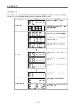
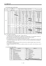
(a) Control modes and I/O signals
Connector Pin No.
Signal
input/output
(Note 1) I/O
(Note 2) Symbols of I/O signals in control modes
Related parameter
P P/S S S/T T T/P
10
I
PP
PP/-
(Note 5)
(Note 5)
(Note 5)
-/PP
PD43/PD44 (Note 4)
13
O
(Note 3)
(Note 3)
(Note 3)
(Note 3)
(Note 3)
(Note 3)
PD47 (Note 4)
14
O
(Note 3)
(Note 3)
(Note 3)
(Note 3)
(Note 3)
(Note 3)
PD47 (Note 4)
15
I
SON SON SON SON SON SON PD03/PD04
16
I
-/SP2 SP2
SP2/SP2
SP2 SP2/- PD05/PD06
17 I
PC
PC/ST1
ST1
ST1/RS2
RS2
RS2/PC
PD07/PD08
18
I
TL TL/ST2 ST2
ST2/RS1
RS1 RS1/TL PD09/PD10
19
I
RES RES RES RES RES RES PD11/PD12
22 O INP
INP/SA
SA SA/- -/INP
PD23
23 O ZSP ZSP ZSP ZSP ZSP ZSP
PD24
CN1 24
O
INP INP/SA SA SA/-
-/INP
PD25
25 O TLC TLC TLC
TLC/VLC
VLC
VLC/TLC PD26
33 O OP OP OP OP OP OP
35
I
NP
NP/-
(Note 5)
(Note 5)
(Note 5)
-/NP
PD45/PD46 (Note 4)
37
(Note 7)
I
PP2
PP2/-
(Note 6)
(Note 6)
(Note 6)
-/PP2
PD43/PD44 (Note 4)
38
(Note 7)
I
NP2
NP2/-
(Note 6)
(Note 6)
(Note 6)
-/NP2
PD45/PD46 (Note 4)
41
I
CR CR/SP1 SP1 SP1/SP1 SP1 SP1/CR PD13/PD14
42
I
EM2 EM2 EM2 EM2 EM2 EM2
43
I
LSP LSP LSP LSP/- -/LSP PD17/PD18
44
I
LSN LSN LSN LSN/- -/LSN PD19/PD20
45
I
LOP LOP LOP LOP LOP LOP PD21/PD22
48 O
ALM ALM ALM ALM ALM ALM
49 O RD RD RD RD RD RD
PD28
Note 1. I: input signal, O: output signal
2. P: position control mode, S: speed control mode, T: torque control mode
P/S: position/speed control switching mode, S/T: speed/torque control switching mode, T/P: torque/position switching mode
3. Output devices are not assigned by default. Assign the output devices with [Pr. PD47] as necessary.
4. This is used with MR-J4-_A_-RJ servo amplifiers with software version B3 or later.
5. This is available as an input device of sink interface. Input devices are not assigned by default. Assign the input devices with
[Pr. PD43] to [Pr. PD46] as necessary. of 24 V DC to CN1-12 pin. Also, this is available with servo amplifiers with
software version B3 or later.
6. This is available as an input device of source interface. Input devices are not assigned by default. Assign the input devices
with [Pr. PD43] to [Pr. PD46] as necessary.
7. These pins are available for MR-J4-_A_(-RJ) servo amplifiers manufactured in January 2015 or later with software version B7
or later.
(b) Symbol and signal names
Symbol Application Symbol Application
SON Servo-on
RES Reset
LSP
Forward rotation stroke end
EM2
Forced stop 2
LSN
Reverse rotation stroke end
LOP
Control switching
CR Clear
TLC Limiting
torque
SP1
Speed selection 1
VLC
Limiting speed
SP2
Speed selection 2
RD
Ready
PC
Proportion control
ZSP
Zero speed detection
ST1
Forward rotation start
INP
In-position
ST2
Reverse rotation start
SA
Speed reached
RS1
Forward rotation selection
ALM
Malfunction
RS2
Reverse rotation selection
OP
Encoder Z-phase pulse (open collector)
TL
External torque limit selection
Summary of Contents for MR-J4-100A(-RJ)
Page 19: ...10 MEMO ...
Page 75: ...1 FUNCTIONS AND CONFIGURATION 1 56 MEMO ...
Page 83: ...2 INSTALLATION 2 8 MEMO ...
Page 159: ...3 SIGNALS AND WIRING 3 76 MEMO ...
Page 203: ...4 STARTUP 4 44 MEMO ...
Page 351: ...7 SPECIAL ADJUSTMENT FUNCTIONS 7 40 MEMO ...
Page 365: ...8 TROUBLESHOOTING 8 14 MEMO ...
Page 387: ...9 DIMENSIONS 9 22 MEMO ...
Page 403: ...10 CHARACTERISTICS 10 16 MEMO ...
Page 553: ...12 ABSOLUTE POSITION DETECTION SYSTEM 12 30 MEMO ...
Page 567: ...13 USING STO FUNCTION 13 14 MEMO ...
Page 607: ...14 COMMUNICATION FUNCTION MITSUBISHI ELECTRIC GENERAL PURPOSE AC SERVO PROTOCOL 14 40 MEMO ...
Page 639: ...15 USING A LINEAR SERVO MOTOR 15 32 MEMO ...
Page 767: ...18 MR J4 03A6 RJ SERVO AMPLIFIER 18 84 MEMO ...
Page 856: ...APPENDIX App 41 ...
Page 905: ...MEMO ...


