
3. SIGNALS AND WIRING
3 - 28
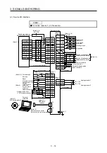
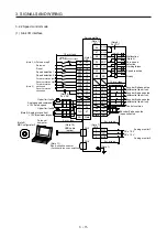
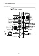
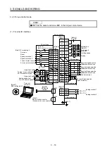
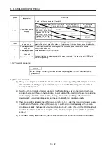
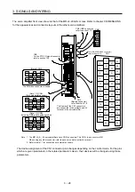
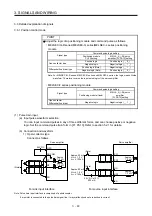
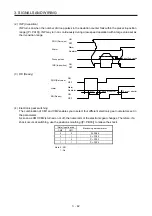
The servo amplifier front view shown is that of the MR-J4-20A-RJ or less. Refer to chapter 9 DIMENSIONS
for the appearances and connector layouts of the other servo amplifiers.
2
LG
3
MO2
1
MO1
CN6
CN1
4
MRR
2
LG
8
6
1
P5
5
10
3
MR
7
9
BAT
(Note 2) CN2
MXR
MX
2
4
6
8
10
12
14
16
18
20
22
24
1
3
5
7
9
11
13
15
17
19
21
23
27
29
31
33
35
37
39
41
43
45
47
49
26
28
30
32
34
36
38
40
42
44
46
48
25
50
4
MRR2
2
LG
8
6
1
P5
5
10
3
MR2
7
9
(Note 1, 2) CN2L
(For using serial encoder)
MXR2
THM2
THM1
MX2
4
PAR
2
LG
8
6
1
P5
PBR
PSEL
PB
5
10
3
PA
7
9
(Note 1, 2) CN2L
(for using A/B/Z-phase pulse encoder)
PZR
PZ
The frames of the CN1 connectors
are connected to the protective earth
terminal in the servo amplifier.
CN5 (USB connector)
refer to section 11.7.
CN3 (RS-422/RS-485 connector)
refer to chapter 14.
The 3M make connector is shown.
CN8
For the STO I/O signal connector,
refer to section 13.2.
(Battery connector)
refer to section 11.8.
CN4
BAT
Note 1. The MR-J4-_A_-RJ servo amplifiers have CN2L connectors. This CN2L is a connector of 3M.
When using any other connector, refer to each servo motor instruction manual.
2. Refer to table 1.1 for connections of external encoders.
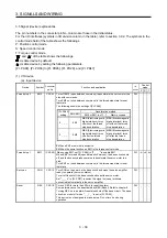
The device assignment of the CN1 connector pins changes depending on the control mode. For the pins
which are given parameters in the related parameter column, their devices will be changed using those
parameters.
Summary of Contents for MR-J4-100A(-RJ)
Page 19: ...10 MEMO ...
Page 75: ...1 FUNCTIONS AND CONFIGURATION 1 56 MEMO ...
Page 83: ...2 INSTALLATION 2 8 MEMO ...
Page 159: ...3 SIGNALS AND WIRING 3 76 MEMO ...
Page 203: ...4 STARTUP 4 44 MEMO ...
Page 351: ...7 SPECIAL ADJUSTMENT FUNCTIONS 7 40 MEMO ...
Page 365: ...8 TROUBLESHOOTING 8 14 MEMO ...
Page 387: ...9 DIMENSIONS 9 22 MEMO ...
Page 403: ...10 CHARACTERISTICS 10 16 MEMO ...
Page 553: ...12 ABSOLUTE POSITION DETECTION SYSTEM 12 30 MEMO ...
Page 567: ...13 USING STO FUNCTION 13 14 MEMO ...
Page 607: ...14 COMMUNICATION FUNCTION MITSUBISHI ELECTRIC GENERAL PURPOSE AC SERVO PROTOCOL 14 40 MEMO ...
Page 639: ...15 USING A LINEAR SERVO MOTOR 15 32 MEMO ...
Page 767: ...18 MR J4 03A6 RJ SERVO AMPLIFIER 18 84 MEMO ...
Page 856: ...APPENDIX App 41 ...
Page 905: ...MEMO ...


