


19. MR-D01 EXTENSION I/O UNIT
19 - 33
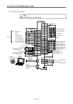
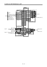
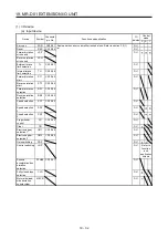
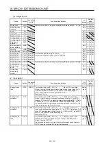
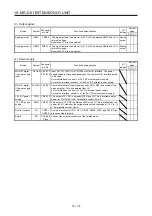
(b) Output device
Device Symbol
Connector
pin No.
Function and application
I/O
division
Control
mode
P S T
Malfunction
ALM
Same as when a servo amplifier is used alone. Refer to section 3.5 (1) (b). DO-1
Dynamic brake
interlock
DB
DO-1
Ready RD
DO-1
In-position INP
CN10-49
DO-1
Speed reached
SA
CN10-49
DO-1
Limiting speed
VLC
DO-1
Limiting torque
TLC
DO-1
Zero speed
detection
ZSP
DO-1
Electromagnetic
brake interlock
MBR
DO-1
Warning WNG
DO-1
Battery warning
BWNG
DO-1
Alarm code 0
ACD0 (CN10-22) To use these signals, set [Pr. Po12] to "_ _ _ 1".
For details of the alarm codes, refer to chapter 8.
DO-1
Alarm code 1
ACD1 (CN10-23)
DO-1
Alarm code 2
ACD2 (CN10-24)
DO-1
Alarm code 3
ACD3 (CN10-25)
DO-1
Absolute position
undetermined
ABSV
Same as when a servo amplifier is used alone. Refer to section 3.5 (1) (b). DO-1
During tough
drive
MTTR
DO-1
During fully
closed loop
control
CLDS
DO-1
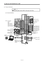
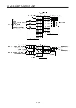
(2) Input signal
Device Symbol
Connector
pin No.
Function and application
I/O
division
Control
mode
P S T
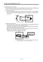
Analog torque
limit
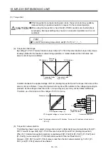
OTLA CN20-12 To use this signal, set [Pr. Po11] to "_ 1 _ _". When OTLA is enabled,
torque is limited in the full servo motor output torque range. Apply 0 V to
+10 V DC between OTLA and LG. C of the power supply to
OTLA. The maximum torque is generated at +10 V.
Resolution: 12 bits
Analog
input
Analog torque
command
OTC
To use this signal, set [Pr. Po11] to "_ 1 _ _". This is used to control
torque in the full servo motor output torque range. Apply 0 V to ±8 V DC
between OTC and LG. The maximum torque is generated at ±8 V. (Refer
to section 3.6.3 (1).) The torque at ±8 V can be changed with [Pr. PC13].
If a value equal to or larger than the maximum torque is input to OTC, the
value is clamped at the maximum torque.
Analog
input
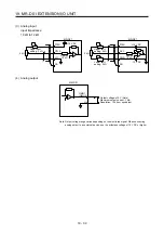
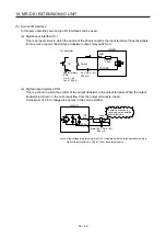
Analog speed
command
OVC
CN20-2 To use this signal, set [Pr. Po11] to "_ _ 1 _". The signal controls the
servo motor setting speed by applying -10 V to +10 V DC to between OVC
and LG. The percentage will be 0% with -10 V, 100% with 0 V, and 200%
with +10 V to the servo motor setting speed.
Resolution: 12 bits
Analog
input
Analog speed
limit
OVLA
To use this signal, set [Pr. Po11] to "_ _ 1 _". Apply 0 V to ±10 V DC
between OVLA and LG. Speed set in [Pr. PC12] is provided at ±10 V.
(Refer to section 3.6.3 (3).)
If a limited value equal to or larger than the permissible speed is input to
OVLA, the value is clamped at the permissible speed.
Analog
input
Summary of Contents for MR-J4-100A(-RJ)
Page 19: ...10 MEMO ...
Page 75: ...1 FUNCTIONS AND CONFIGURATION 1 56 MEMO ...
Page 83: ...2 INSTALLATION 2 8 MEMO ...
Page 159: ...3 SIGNALS AND WIRING 3 76 MEMO ...
Page 203: ...4 STARTUP 4 44 MEMO ...
Page 351: ...7 SPECIAL ADJUSTMENT FUNCTIONS 7 40 MEMO ...
Page 365: ...8 TROUBLESHOOTING 8 14 MEMO ...
Page 387: ...9 DIMENSIONS 9 22 MEMO ...
Page 403: ...10 CHARACTERISTICS 10 16 MEMO ...
Page 553: ...12 ABSOLUTE POSITION DETECTION SYSTEM 12 30 MEMO ...
Page 567: ...13 USING STO FUNCTION 13 14 MEMO ...
Page 607: ...14 COMMUNICATION FUNCTION MITSUBISHI ELECTRIC GENERAL PURPOSE AC SERVO PROTOCOL 14 40 MEMO ...
Page 639: ...15 USING A LINEAR SERVO MOTOR 15 32 MEMO ...
Page 767: ...18 MR J4 03A6 RJ SERVO AMPLIFIER 18 84 MEMO ...
Page 856: ...APPENDIX App 41 ...
Page 905: ...MEMO ...


