

11. OPTIONS AND PERIPHERAL EQUIPMENT
11 - 93
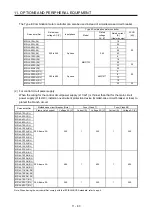
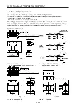
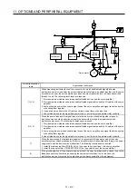
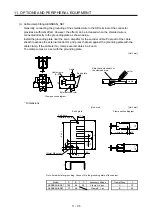
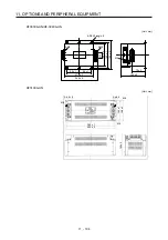
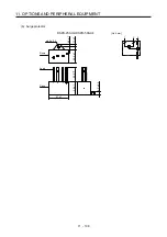
Instrument
Receiver
Servo
amplifier
Servo motor
M
2)
2)
8)
1)
7)
7)
7)
5)
3)
4)
6)
3)
Sensor
power
supply
Sensor
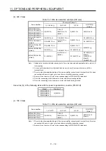
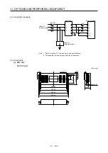
Noise transmission
route
Suppression techniques
1) 2) 3)
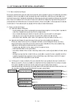
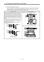
When measuring instruments, receivers, sensors, etc. which handle weak signals and may
malfunction due to noise and/or their signal cables are contained in a cabinet together with the servo
amplifier or run near the servo amplifier, such devices may malfunction due to noises transmitted
through the air. The following techniques are required.
1. Provide maximum clearance between easily affected devices and the servo amplifier.
2. Provide maximum clearance between easily affected signal cables and the I/O cables of the servo
amplifier.
3. Avoid wiring the power lines (input/output lines of the servo amplifier) and signal lines side by side
or bundling them together.
4. Insert a line noise filter to the I/O cables or a radio noise filter on the input line.
5. Use shielded wires for the signal and power lines, or put the lines in separate metal conduits.
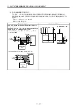
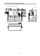
4) 5) 6)
When the power lines and the signal lines are laid side by side or bundled together, magnetic
induction noise and static induction noise will be transmitted through the signal cables and
malfunction may occur. The following techniques are required.
1. Provide maximum clearance between easily affected devices and the servo amplifier.
2. Provide maximum clearance between easily affected signal cables and the I/O cables of the servo
amplifier.
3. Avoid wiring the power lines (input/output lines of the servo amplifier) and signal lines side by side
or bundling them together.
4. Use shielded wires for the signal and power lines, or put the lines in separate metal conduits.
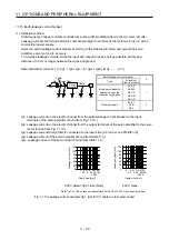
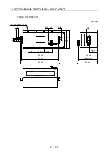
7)
When the power supply of peripheral equipment is connected to the power supply of the servo
amplifier system, noises produced by the servo amplifier may be transmitted back through the power
supply cable and the devices may malfunction. The following techniques are required.
1. Install the radio noise filter (FR-BIF(-H)) on the power lines (Input lines) of the servo amplifier.
2. Install the line noise filter (FR-BSF01/FR-BLF) on the power lines of the servo amplifier.
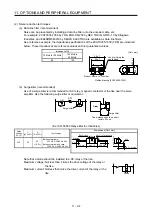
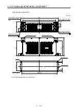
8)
If the grounding wires of the peripheral equipment and the servo amplifier make a closed loop circuit,
leakage current may flow through, causing the equipment to malfunction. In this case, the
malfunction may be prevented by the grounding wires disconnected from the equipment.
Summary of Contents for MR-J4-100A(-RJ)
Page 19: ...10 MEMO ...
Page 75: ...1 FUNCTIONS AND CONFIGURATION 1 56 MEMO ...
Page 83: ...2 INSTALLATION 2 8 MEMO ...
Page 159: ...3 SIGNALS AND WIRING 3 76 MEMO ...
Page 203: ...4 STARTUP 4 44 MEMO ...
Page 351: ...7 SPECIAL ADJUSTMENT FUNCTIONS 7 40 MEMO ...
Page 365: ...8 TROUBLESHOOTING 8 14 MEMO ...
Page 387: ...9 DIMENSIONS 9 22 MEMO ...
Page 403: ...10 CHARACTERISTICS 10 16 MEMO ...
Page 553: ...12 ABSOLUTE POSITION DETECTION SYSTEM 12 30 MEMO ...
Page 567: ...13 USING STO FUNCTION 13 14 MEMO ...
Page 607: ...14 COMMUNICATION FUNCTION MITSUBISHI ELECTRIC GENERAL PURPOSE AC SERVO PROTOCOL 14 40 MEMO ...
Page 639: ...15 USING A LINEAR SERVO MOTOR 15 32 MEMO ...
Page 767: ...18 MR J4 03A6 RJ SERVO AMPLIFIER 18 84 MEMO ...
Page 856: ...APPENDIX App 41 ...
Page 905: ...MEMO ...


