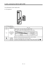

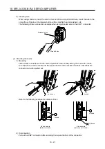

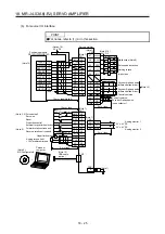
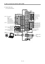
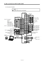
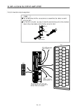
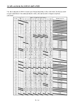
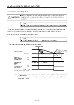

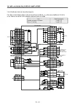
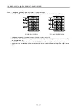
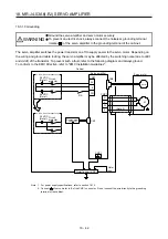

18. MR-J4-03A6(-RJ) SERVO AMPLIFIER
18 - 33
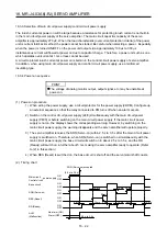
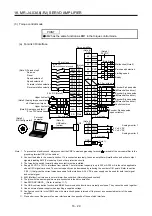
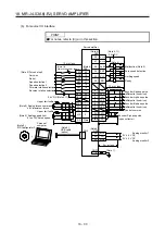
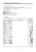
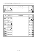
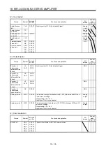
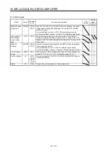
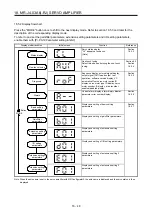
Note 1. I: input signal, O: output signal
2. P: position control mode, S: speed control mode, T: torque control mode, P/S: position/speed control switching
mode, S/T: speed/torque control switching mode, T/P: torque/position control switching mode
3. TLA will be available when TL (External torque limit selection) is enabled with [Pr. PD03] to [Pr. PD22].
4. This is available as an input device of sink interface. Input devices are not assigned by default. Assign the input
devices with [Pr. PD43] to [Pr. PD46] as necessary. When using this pin by DI, of 24 V DC to CN1-12
pin.
5. This is available as an input device of source interface. Input devices are not assigned by default. Assign the
input devices with [Pr. PD43] to [Pr. PD46] as necessary.
Summary of Contents for MR-J4-100A(-RJ)
Page 19: ...10 MEMO ...
Page 75: ...1 FUNCTIONS AND CONFIGURATION 1 56 MEMO ...
Page 83: ...2 INSTALLATION 2 8 MEMO ...
Page 159: ...3 SIGNALS AND WIRING 3 76 MEMO ...
Page 203: ...4 STARTUP 4 44 MEMO ...
Page 351: ...7 SPECIAL ADJUSTMENT FUNCTIONS 7 40 MEMO ...
Page 365: ...8 TROUBLESHOOTING 8 14 MEMO ...
Page 387: ...9 DIMENSIONS 9 22 MEMO ...
Page 403: ...10 CHARACTERISTICS 10 16 MEMO ...
Page 553: ...12 ABSOLUTE POSITION DETECTION SYSTEM 12 30 MEMO ...
Page 567: ...13 USING STO FUNCTION 13 14 MEMO ...
Page 607: ...14 COMMUNICATION FUNCTION MITSUBISHI ELECTRIC GENERAL PURPOSE AC SERVO PROTOCOL 14 40 MEMO ...
Page 639: ...15 USING A LINEAR SERVO MOTOR 15 32 MEMO ...
Page 767: ...18 MR J4 03A6 RJ SERVO AMPLIFIER 18 84 MEMO ...
Page 856: ...APPENDIX App 41 ...
Page 905: ...MEMO ...


