

APPENDIX
App. - 35
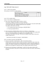
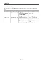
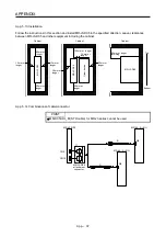
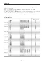
App. 5.11 Troubleshooting
When power is not supplied or FAULT LED turns on, refer the following table and take the appropriate
action.
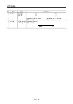
Event Description
Cause
Action
Power is not supplied.
Power LED does not turn on
although power is supplied.
1. 24 V DC power supply is
malfunctioning.
Replace the 24 V DC power supply.
2. Wires between MR-J3-D05 and 24
V DC power supply are
disconnected or are in contact with
other wires.
Check the wiring.
3. MR-J3-D05 is malfunctioning.
Replace the MR-J3-D05.
FAULT LED is on.
FAULT LED of A-axis or B-
axis is on, and will not turn
off.
1. The delay time settings are not
matched.
Check the settings of the rotary
switch.
2. Switch input error
Check the wiring or sequence of the
input signals.
3. TOF signal error
Check the connection with the servo
amplifier.
4. MR-J3-D05 is malfunctioning.
Replace the MR-J3-D05.
Summary of Contents for MR-J4-100A(-RJ)
Page 19: ...10 MEMO ...
Page 75: ...1 FUNCTIONS AND CONFIGURATION 1 56 MEMO ...
Page 83: ...2 INSTALLATION 2 8 MEMO ...
Page 159: ...3 SIGNALS AND WIRING 3 76 MEMO ...
Page 203: ...4 STARTUP 4 44 MEMO ...
Page 351: ...7 SPECIAL ADJUSTMENT FUNCTIONS 7 40 MEMO ...
Page 365: ...8 TROUBLESHOOTING 8 14 MEMO ...
Page 387: ...9 DIMENSIONS 9 22 MEMO ...
Page 403: ...10 CHARACTERISTICS 10 16 MEMO ...
Page 553: ...12 ABSOLUTE POSITION DETECTION SYSTEM 12 30 MEMO ...
Page 567: ...13 USING STO FUNCTION 13 14 MEMO ...
Page 607: ...14 COMMUNICATION FUNCTION MITSUBISHI ELECTRIC GENERAL PURPOSE AC SERVO PROTOCOL 14 40 MEMO ...
Page 639: ...15 USING A LINEAR SERVO MOTOR 15 32 MEMO ...
Page 767: ...18 MR J4 03A6 RJ SERVO AMPLIFIER 18 84 MEMO ...
Page 856: ...APPENDIX App 41 ...
Page 905: ...MEMO ...


