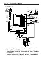
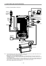
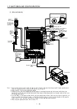
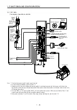


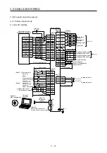
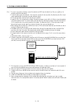
3. SIGNALS AND WIRING
3 - 2
CAUTION
Connecting a servo motor of the wrong axis to U, V, W, or CN2 of the servo
amplifier may cause a malfunction.
Before wiring, switch operation, etc., eliminate static electricity. Otherwise, it may
cause a malfunction.
POINT
When you use a linear servo motor, replace the following words in the left to the
words in the right.
Load to motor inertia ratio
→
Load to motor mass ratio
Torque
→
Thrust
(Servo motor) speed
→
(Linear servo motor) speed
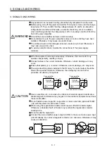
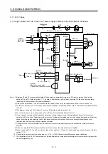
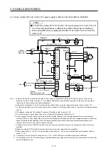
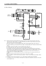
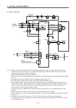
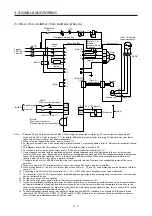
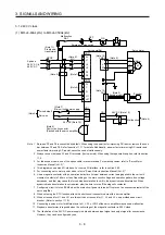
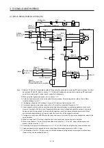
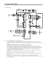
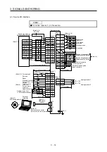
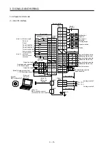
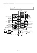
3.1 Input power supply circuit
CAUTION
Always connect a magnetic contactor between the power supply and the main
circuit power supply (L1/L2/L3) of the servo amplifier, in order to configure a
circuit that shuts down the power supply on the side of the servo amplifier’s power
supply. If a magnetic contactor is not connected, continuous flow of a large
current may cause a fire when the servo amplifier malfunctions.
Use ALM (Malfunction) to switch main circuit power supply off. Not doing so may
cause a fire when a regenerative transistor malfunctions or the like may overheat
the regenerative resistor.
Check the servo amplifier model, and then input proper voltage to the servo
amplifier power supply. If input voltage exceeds the upper limit of the
specification, the servo amplifier will break down.
The servo amplifier has a built-in surge absorber (varistor) to reduce exogenous
noise and to suppress lightning surge. Exogenous noise or lightning surge
deteriorates the varistor characteristics, and the varistor may be damaged. To
prevent a fire, use a molded-case circuit breaker or fuse for input power supply.
Connecting a servo motor of the wrong axis to U, V, W, or CN2 of the servo
amplifier may cause a malfunction.
The N- terminal is not a neutral point of the power supply. Incorrect wiring will
cause a burst, damage, etc.
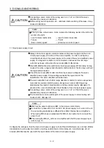
POINT
EM2 has the same function as EM1 in the torque control mode.
Connect the 1-phase 200 V AC to 240 V AC power supply to L1 and L3. One of
the connecting destinations is different from MR-J3 Series Servo Amplifier's.
When using MR-J4 as a replacement for MR-J3, be careful not to connect the
power to L2.
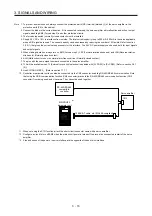
When using the MR-J4-_A-RJ servo amplifier with the DC power supply input,
refer to app. 13.
Configure the wirings so that the main circuit power supply is shut off and SON (Servo-on) is turned off after
deceleration to a stop due to an alarm occurring, enabled servo forced stop, etc. A molded-case circuit
breaker (MCCB) must be used with the input cables of the main circuit power supply.
Summary of Contents for MR-J4-100A(-RJ)
Page 19: ...10 MEMO ...
Page 75: ...1 FUNCTIONS AND CONFIGURATION 1 56 MEMO ...
Page 83: ...2 INSTALLATION 2 8 MEMO ...
Page 159: ...3 SIGNALS AND WIRING 3 76 MEMO ...
Page 203: ...4 STARTUP 4 44 MEMO ...
Page 351: ...7 SPECIAL ADJUSTMENT FUNCTIONS 7 40 MEMO ...
Page 365: ...8 TROUBLESHOOTING 8 14 MEMO ...
Page 387: ...9 DIMENSIONS 9 22 MEMO ...
Page 403: ...10 CHARACTERISTICS 10 16 MEMO ...
Page 553: ...12 ABSOLUTE POSITION DETECTION SYSTEM 12 30 MEMO ...
Page 567: ...13 USING STO FUNCTION 13 14 MEMO ...
Page 607: ...14 COMMUNICATION FUNCTION MITSUBISHI ELECTRIC GENERAL PURPOSE AC SERVO PROTOCOL 14 40 MEMO ...
Page 639: ...15 USING A LINEAR SERVO MOTOR 15 32 MEMO ...
Page 767: ...18 MR J4 03A6 RJ SERVO AMPLIFIER 18 84 MEMO ...
Page 856: ...APPENDIX App 41 ...
Page 905: ...MEMO ...


