


11. OPTIONS AND PERIPHERAL EQUIPMENT
11 - 79
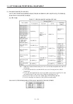
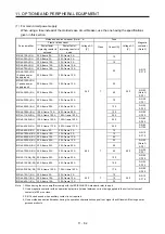
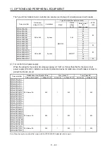
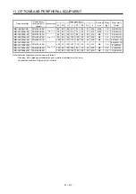
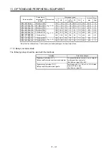
(b) 400 V class
Table 11.2 Wire size selection example (HIV wire)
Servo amplifier
Wires
[mm
2
] (Note 1)
1) L1/L2/L3/
2) L11/L21
3) P+/C
4) U/V/W/
(Note 3)
MR-J4-60A4(-RJ)
MR-J4-100A4(-RJ)
2 (AWG 14)
1.25 to 2
(AWG 16 to 14)
(Note 4)
2 (AWG 14)
AWG 16 to 14
MR-J4-200A4(-RJ)
MR-J4-350A4(-RJ)
MR-J4-500A4(-RJ)
(Note 2)
2 (AWG 14): b
1.25 (AWG 16): a
2 (AWG 14): c
(Note 4)
2 (AWG 14): b
3.5 (AWG 12): a
MR-J4-700A4(-RJ)
(Note 2)
3.5 (AWG 12): a
5.5 (AWG 10): a
MR-J4-11KA4(-RJ)
(Note 2)
5.5 (AWG 10): d
1.25 (AWG 16): b
2 (AWG 14): b
(Note 4)
2 (AWG 14): f
8 (AWG 8): g
MR-J4-15KA4(-RJ)
(Note 2)
8 (AWG 8): g
3.5 (AWG 12): d
MR-J4-22KA4(-RJ)
(Note 2)
14 (AWG 6): i
3.5 (AWG 12): e
5.5 (AWG 10): e
(Note 5)
8 (AWG 8): h
(Note 6)
14 (AWG 6): i
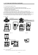
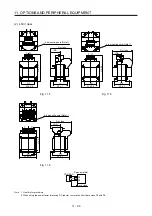
Note 1. Alphabets in the table indicate crimping tools. For crimp terminals and applicable tools, refer to (2)
in this section.
2. To connect these models to a terminal block, be sure to use the screws that come with the
terminal block.
3. The wire size shows applicable size of the servo amplifier connector and terminal block. For wires
connecting to the servo motor, refer to each servo amplifier instruction manual.
4. Be sure to use the size of 2 mm
2
when corresponding to IEC/EN/UL/CSA standard.
5. This is for connecting to the linear servo motor with natural cooling method.
6. This is for connecting to the linear servo motor with liquid cooling method.
Use wires (5)) of the following sizes with the power regeneration converter (FR-RC-H).
Model Wire
[mm
2
]
FR-RC-H15K
14 (AWG 6)
FR-RC-H30K
FR-RC-H55K
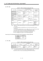
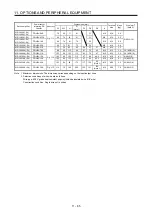
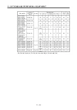
(c) 100 V class
Table 11.3 Wire size selection example (HIV wire)
Servo amplifier
Wires
[mm
2
]
1) L1/L2/
2) L11/L21
3) P+/C
4) U/V/W/
(Note 1)
MR-J4-10A1(-RJ)
2 (AWG 14)
1.25 to 2
(AWG 16 to 14)
(Note 2)
2 (AWG 14)
AWG 18 to 14
(Note 2)
MR-J4-20A1(-RJ)
MR-J4-40A1(-RJ)
Note 1. The wire size shows applicable size of the servo amplifier connector and terminal block. For wires
connecting to the servo motor, refer to each servo amplifier instruction manual.
2. Be sure to use the size of 2 mm
2
when corresponding to IEC/EN/UL/CSA standard.
Summary of Contents for MR-J4-100A(-RJ)
Page 19: ...10 MEMO ...
Page 75: ...1 FUNCTIONS AND CONFIGURATION 1 56 MEMO ...
Page 83: ...2 INSTALLATION 2 8 MEMO ...
Page 159: ...3 SIGNALS AND WIRING 3 76 MEMO ...
Page 203: ...4 STARTUP 4 44 MEMO ...
Page 351: ...7 SPECIAL ADJUSTMENT FUNCTIONS 7 40 MEMO ...
Page 365: ...8 TROUBLESHOOTING 8 14 MEMO ...
Page 387: ...9 DIMENSIONS 9 22 MEMO ...
Page 403: ...10 CHARACTERISTICS 10 16 MEMO ...
Page 553: ...12 ABSOLUTE POSITION DETECTION SYSTEM 12 30 MEMO ...
Page 567: ...13 USING STO FUNCTION 13 14 MEMO ...
Page 607: ...14 COMMUNICATION FUNCTION MITSUBISHI ELECTRIC GENERAL PURPOSE AC SERVO PROTOCOL 14 40 MEMO ...
Page 639: ...15 USING A LINEAR SERVO MOTOR 15 32 MEMO ...
Page 767: ...18 MR J4 03A6 RJ SERVO AMPLIFIER 18 84 MEMO ...
Page 856: ...APPENDIX App 41 ...
Page 905: ...MEMO ...


