


7
14.5.10 Alarm history ....................................................................................................................... 14-37
14.5.11 Current alarm ...................................................................................................................... 14-38
14.5.12 Other commands................................................................................................................. 14-39
15. USING A LINEAR SERVO MOTOR
15- 1 to 15-32
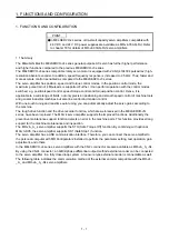
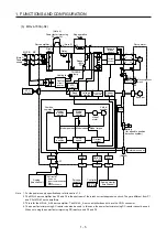
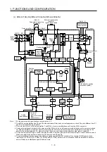
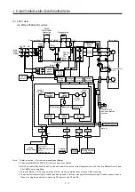
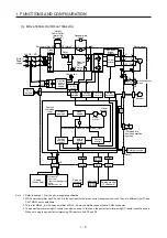
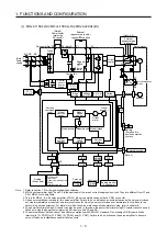
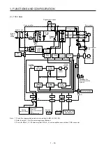
15.1 Functions and configuration ......................................................................................................... 15- 1
15.1.1 Summary ................................................................................................................................ 15- 1
15.1.2 Configuration including peripheral equipment ....................................................................... 15- 2
15.2 Signals and wiring ......................................................................................................................... 15- 6
15.3 Operation and functions ................................................................................................................ 15- 7
15.3.1 Startup .................................................................................................................................... 15- 7
15.3.2 Magnetic pole detection ........................................................................................................ 15-11
15.3.3 Home position return ............................................................................................................. 15-18
15.3.4 Test operation mode in MR Configurator2 ............................................................................ 15-23
15.3.5 Function................................................................................................................................. 15-24
15.3.6 Absolute position detection system ....................................................................................... 15-27
15.4 Characteristics ............................................................................................................................. 15-28
15.4.1 Overload protection characteristics ...................................................................................... 15-28
15.4.2 Power supply capacity and generated loss .......................................................................... 15-29
15.4.3 Dynamic brake characteristics .............................................................................................. 15-30
15.4.4 Permissible load to motor mass ratio when the dynamic brake is used ............................... 15-31
16. USING A DIRECT DRIVE MOTOR
16- 1 to 16-20
16.1 Functions and configuration ......................................................................................................... 16- 1
16.1.1 Summary ................................................................................................................................ 16- 1
16.1.2 Configuration including peripheral equipment ....................................................................... 16- 2
16.2 Signals and wiring ......................................................................................................................... 16- 3
16.3 Operation and functions ................................................................................................................ 16- 4
16.3.1 Startup procedure .................................................................................................................. 16- 5
16.3.2 Magnetic pole detection ......................................................................................................... 16- 6
16.3.3 Function................................................................................................................................. 16-12
16.4 Absolute position detection system ............................................................................................. 16-14
16.5 Characteristics ............................................................................................................................. 16-15
16.5.1 Overload protection characteristics ...................................................................................... 16-15
16.5.2 Power supply capacity and generated loss .......................................................................... 16-17
16.5.3 Dynamic brake characteristics .............................................................................................. 16-18
17. FULLY CLOSED LOOP SYSTEM
17- 1 to 17-24
17.1 Functions and configuration ......................................................................................................... 17- 2
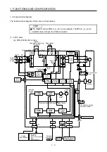
17.1.1 Function block diagram .......................................................................................................... 17- 2
17.1.2 Selecting procedure of control mode ..................................................................................... 17- 3
17.1.3 System configuration
.............................................................................................................. 17- 4
17.2 Load-side encoder ........................................................................................................................ 17- 6
17.2.1 Linear encoder ....................................................................................................................... 17- 6
17.2.2 Rotary encoder
....................................................................................................................... 17- 6
17.2.3 Configuration diagram of encoder cable ................................................................................ 17- 7
17.2.4 MR-J4FCCBL03M branch cable ............................................................................................ 17- 9
17.3 Operation and functions ............................................................................................................... 17-10
Summary of Contents for MR-J4-100A(-RJ)
Page 19: ...10 MEMO ...
Page 75: ...1 FUNCTIONS AND CONFIGURATION 1 56 MEMO ...
Page 83: ...2 INSTALLATION 2 8 MEMO ...
Page 159: ...3 SIGNALS AND WIRING 3 76 MEMO ...
Page 203: ...4 STARTUP 4 44 MEMO ...
Page 351: ...7 SPECIAL ADJUSTMENT FUNCTIONS 7 40 MEMO ...
Page 365: ...8 TROUBLESHOOTING 8 14 MEMO ...
Page 387: ...9 DIMENSIONS 9 22 MEMO ...
Page 403: ...10 CHARACTERISTICS 10 16 MEMO ...
Page 553: ...12 ABSOLUTE POSITION DETECTION SYSTEM 12 30 MEMO ...
Page 567: ...13 USING STO FUNCTION 13 14 MEMO ...
Page 607: ...14 COMMUNICATION FUNCTION MITSUBISHI ELECTRIC GENERAL PURPOSE AC SERVO PROTOCOL 14 40 MEMO ...
Page 639: ...15 USING A LINEAR SERVO MOTOR 15 32 MEMO ...
Page 767: ...18 MR J4 03A6 RJ SERVO AMPLIFIER 18 84 MEMO ...
Page 856: ...APPENDIX App 41 ...
Page 905: ...MEMO ...


