


5. PARAMETERS
5 - 2
5.1 Parameter list
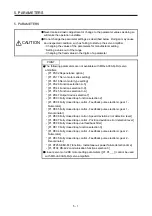
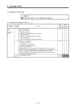
POINT
To enable a parameter whose symbol is preceded by *, cycle the power after
setting it.
Abbreviations of operation modes indicate the followings.
Standard: Standard (semi closed loop system) use of the rotary servo motor
Full.: Fully closed loop system use of the rotary servo motor
Lin.: Linear servo motor use
DD: Direct drive (DD) motor use
For MR-J4-03A6(-RJ) servo amplifiers, the operation mode is available only in
standard (semi closed loop system).
The symbols in the control mode column mean as follows.
P: Position control mode
S: Speed control mode
T: Torque control mode
For servo amplifier with software version B3 or later, the parameter initial values
for the manufacturer setting are partially changed.
Setting an out of range value to each parameter will trigger [AL. 37 Parameter
error].
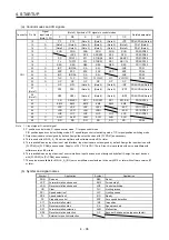
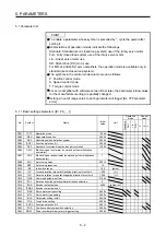
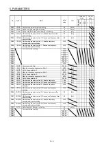
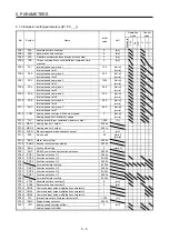
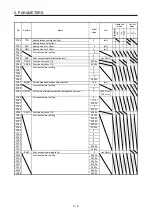
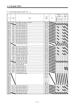
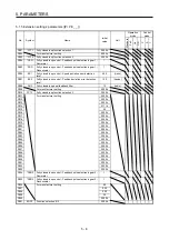
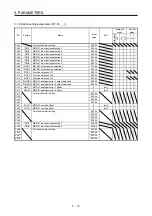
5.1.1 Basic setting parameters ([Pr. PA_ _ ])
No. Symbol
Name
Initial
value
Unit
Operation
mode
Control
mode
Standard
F
ull.
Lin.
D.D.
P
S
T
PA01 *STY Operation
mode
1000h
PA02 *REG Regenerative
option
0000h
PA03
*ABS
Absolute position detection system
0000h
PA04
*AOP1 Function selection A-1
2000h
PA05
*FBP
Number of command input pulses per revolution
10000
PA06
CMX
Electronic gear numerator (command pulse multiplication
numerator)
1
PA07
CDV
Electronic gear denominator (command pulse multiplication
denominator)
1
PA08
ATU
Auto tuning mode
0001h
PA09
RSP
Auto tuning response
16
PA10 INP In-position
range
100
[pulse]
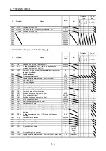
PA11
TLP
Forward rotation torque limit/positive direction thrust limit
100.0
[%]
PA12
TLN
Reverse rotation torque limit/negative direction thrust limit
100.0
[%]
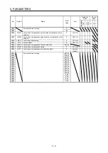
PA13
*PLSS
Command pulse input form
0100h
PA14
*POL
Rotation direction selection/travel direction selection
0
PA15
*ENR
Encoder output pulses
4000
[pulse/rev]
PA16
*ENR2 Encoder output pulses 2
1
PA17
*MSR
Servo motor series setting
0000h
PA18
*MTY
Servo motor type setting
0000h
PA19
*BLK
Parameter writing inhibit
00AAh
PA20
*TDS
Tough drive setting
0000h
PA21
*AOP3 Function selection A-3
0001h
PA22
*PCS
Position control composition selection
0000h
PA23
DRAT
Drive recorder arbitrary alarm trigger setting
0000h
Summary of Contents for MR-J4-100A(-RJ)
Page 19: ...10 MEMO ...
Page 75: ...1 FUNCTIONS AND CONFIGURATION 1 56 MEMO ...
Page 83: ...2 INSTALLATION 2 8 MEMO ...
Page 159: ...3 SIGNALS AND WIRING 3 76 MEMO ...
Page 203: ...4 STARTUP 4 44 MEMO ...
Page 351: ...7 SPECIAL ADJUSTMENT FUNCTIONS 7 40 MEMO ...
Page 365: ...8 TROUBLESHOOTING 8 14 MEMO ...
Page 387: ...9 DIMENSIONS 9 22 MEMO ...
Page 403: ...10 CHARACTERISTICS 10 16 MEMO ...
Page 553: ...12 ABSOLUTE POSITION DETECTION SYSTEM 12 30 MEMO ...
Page 567: ...13 USING STO FUNCTION 13 14 MEMO ...
Page 607: ...14 COMMUNICATION FUNCTION MITSUBISHI ELECTRIC GENERAL PURPOSE AC SERVO PROTOCOL 14 40 MEMO ...
Page 639: ...15 USING A LINEAR SERVO MOTOR 15 32 MEMO ...
Page 767: ...18 MR J4 03A6 RJ SERVO AMPLIFIER 18 84 MEMO ...
Page 856: ...APPENDIX App 41 ...
Page 905: ...MEMO ...


