


3. SIGNALS AND WIRING
3 - 59
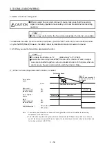
3.8 Alarm occurrence timing chart
CAUTION
When an alarm has occurred, remove its cause, make sure that the operation
signal is not being inputted, ensure safety, and reset the alarm before restarting
operation.
POINT
In the torque control mode, the forced stop deceleration function is not available.
To deactivate an alarm, cycle the control circuit power, push the "SET" button in the current alarm window,
or cycle the RES (Reset) However, the alarm cannot be deactivated unless its cause is removed.
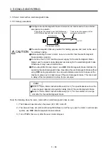
3.8.1 When you use the forced stop deceleration function
POINT
To enable the function, set "2 _ _ _ (initial value)" in [Pr. PA04].
Disable the forced stop deceleration function for a machine in which multiple
axes are connected together, such as a tandem structure. In this case, when an
alarm occurs, the servo motor will stop with the dynamic brake.
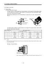
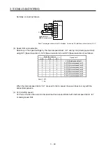
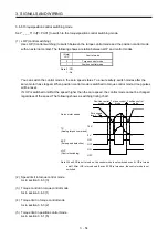
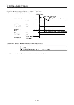
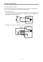
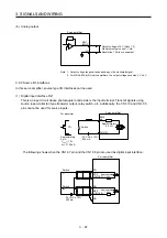
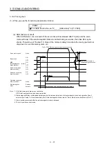
(1) When the forced stop deceleration function is enabled
Command is not received.
Alarm occurrence
Alarm No.
No alarm
(Note 2)
(Note 1)
Model speed command 0
and equal to or less than
zero speed
MBR
(Electromagnetic
brake interlock)
ON
OFF
ON (no alarm)
OFF (alarm)
Base circuit
(Energy supply to
the servo motor)
ON
OFF
Servo amplifier
display
0 r/min
Servo motor
speed
ALM (Malfunction)
Note 1. The model speed command is a speed command generated in the servo amplifier for forced stop
deceleration of the servo motor.
2. This is for when the electronic dynamic brake is enabled with [Pr. PF09] while a certain servo motor is
used. If the servo motor speed is 5 r/min or higher, the electronic dynamic brake will operate continuously
for the time period set in [Pr. PF15].
Summary of Contents for MR-J4-100A(-RJ)
Page 19: ...10 MEMO ...
Page 75: ...1 FUNCTIONS AND CONFIGURATION 1 56 MEMO ...
Page 83: ...2 INSTALLATION 2 8 MEMO ...
Page 159: ...3 SIGNALS AND WIRING 3 76 MEMO ...
Page 203: ...4 STARTUP 4 44 MEMO ...
Page 351: ...7 SPECIAL ADJUSTMENT FUNCTIONS 7 40 MEMO ...
Page 365: ...8 TROUBLESHOOTING 8 14 MEMO ...
Page 387: ...9 DIMENSIONS 9 22 MEMO ...
Page 403: ...10 CHARACTERISTICS 10 16 MEMO ...
Page 553: ...12 ABSOLUTE POSITION DETECTION SYSTEM 12 30 MEMO ...
Page 567: ...13 USING STO FUNCTION 13 14 MEMO ...
Page 607: ...14 COMMUNICATION FUNCTION MITSUBISHI ELECTRIC GENERAL PURPOSE AC SERVO PROTOCOL 14 40 MEMO ...
Page 639: ...15 USING A LINEAR SERVO MOTOR 15 32 MEMO ...
Page 767: ...18 MR J4 03A6 RJ SERVO AMPLIFIER 18 84 MEMO ...
Page 856: ...APPENDIX App 41 ...
Page 905: ...MEMO ...


