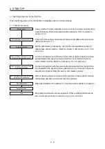


4. STARTUP
4 - 5
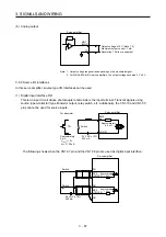
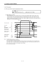
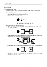
b) When you use a regenerative option for 5 kW or more servo amplifiers
For 5 kW or 7 kW servo amplifiers, the lead wire of the built-in regenerative resistor
connected to P+ terminal and C terminal should not be connected.
The regenerative option should be connected to P+ terminal and C terminal.
Twisted wires should be used. (Refer to section 11.2.4.)
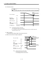
c) When you use a brake unit and power regeneration converter for 5 kW or more servo
amplifiers
For 5 kW or 7 kW servo amplifiers, the lead wire of built-in regenerative resistor connected
to P+ terminal and C terminal should not be connected.
Brake unit, power regeneration converter should be connected to P+ terminal and N-
terminal. (Refer to section 11.3 and 11.4.)
Twisted wires should be used when wiring is over 5 m and equal to or less than 10 m using
a brake unit. (Refer to section 11.3)
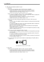
d) When you use a power regeneration common converter for 11 kW or more servo amplifiers
Power regeneration common converter should be connected to P4 terminal and N- terminal.
(Refer to section 11.5.)
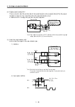
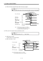
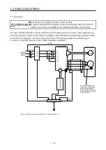
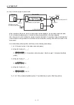
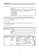
e) The power factor improving DC reactor should be connected between P3 and P4. (Refer to
section 11.11.)
(Note)
Power factor improving
DC reactor
Servo amplifier
P3
P4
Note. Always disconnect between P3 and P4.
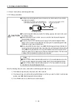
3) 100 V class
The lead wire between P+ terminal and D terminal should not be connected.
The regenerative option should be connected to P+ terminal and C terminal.
Twisted wires should be used. (Refer to section 11.2.4.)
(2) I/O signal wiring
(a) The I/O signals should be connected correctly.
Use DO forced output to forcibly turn on/off the pins of the CN1 connector. You can use this function
to check the wiring. In this case, switch on the control circuit power supply only.
Refer to section 3.2 for details of I/O signal connection.
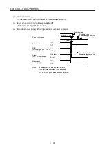
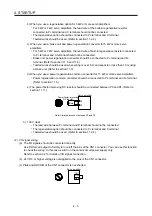
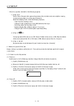
(b) 24 V DC or higher voltage is not applied to the pins of the CN1 connector.
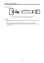
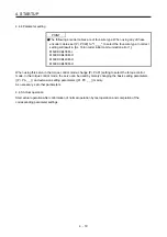
(c) Plate and DOCOM of the CN1 connector is not shorted.
Servo amplifier
DOCOM
Plate
CN1
Summary of Contents for MR-J4-100A(-RJ)
Page 19: ...10 MEMO ...
Page 75: ...1 FUNCTIONS AND CONFIGURATION 1 56 MEMO ...
Page 83: ...2 INSTALLATION 2 8 MEMO ...
Page 159: ...3 SIGNALS AND WIRING 3 76 MEMO ...
Page 203: ...4 STARTUP 4 44 MEMO ...
Page 351: ...7 SPECIAL ADJUSTMENT FUNCTIONS 7 40 MEMO ...
Page 365: ...8 TROUBLESHOOTING 8 14 MEMO ...
Page 387: ...9 DIMENSIONS 9 22 MEMO ...
Page 403: ...10 CHARACTERISTICS 10 16 MEMO ...
Page 553: ...12 ABSOLUTE POSITION DETECTION SYSTEM 12 30 MEMO ...
Page 567: ...13 USING STO FUNCTION 13 14 MEMO ...
Page 607: ...14 COMMUNICATION FUNCTION MITSUBISHI ELECTRIC GENERAL PURPOSE AC SERVO PROTOCOL 14 40 MEMO ...
Page 639: ...15 USING A LINEAR SERVO MOTOR 15 32 MEMO ...
Page 767: ...18 MR J4 03A6 RJ SERVO AMPLIFIER 18 84 MEMO ...
Page 856: ...APPENDIX App 41 ...
Page 905: ...MEMO ...


