


18. MR-J4-03A6(-RJ) SERVO AMPLIFIER
18 - 77
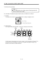
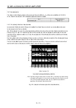
(1) Dynamic brake operation
(a) Calculation of coasting distance
Fig. 18.2 shows the pattern in which the servo motor comes to a stop when the dynamic brake is
operated. Use equation 18.1 to calculate an approximate coasting distance to a stop. The dynamic
brake time constant
τ
varies with the servo motor and machine operation speeds. (Refer to (1) (b) in
this section.)
A working part generally has a friction force. Therefore, actual coasting distance will be shorter than
a maximum coasting distance calculated with the following equation.
V
0
OFF
ON
Machine speed
t
e
Time
EM1 (Forced stop 1)
Dynamic brake
time constant
τ
Fig. 18.2 Dynamic brake operation diagram
L
max
=
60
V
0
•
J
M
t
e
+
1 + J
L
··························································································· (18.1)
L
max
: Maximum coasting distance ······················································································ [mm]
V
0
: Machine's fast feed speed ····················································································· [mm/min]
J
M
: Moment of inertia of the servo motor ································································· [× 10
-4
kg•m
2
]
J
L
: Load moment of inertia converted into equivalent value on servo motor shaft ············· [× 10
-4
kg•m
2
]
τ
: Dynamic brake time constant [s]
t
e
: Delay time of control section ···························································································· [s]
The processing delay time about 3.5 ms.
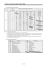
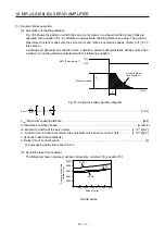
(b) Dynamic brake time constant
The following shows necessary dynamic brake time constant
τ
for equation 18.1.
0
Speed [r/min]
0
1000 2000
0.0005
0.0010
0.0015
0.0020
0.0025
3000 4000 5000 6000
0236
0336
0136
Dynamic brake time
constant [s]
HG-AK series
Summary of Contents for MR-J4-100A(-RJ)
Page 19: ...10 MEMO ...
Page 75: ...1 FUNCTIONS AND CONFIGURATION 1 56 MEMO ...
Page 83: ...2 INSTALLATION 2 8 MEMO ...
Page 159: ...3 SIGNALS AND WIRING 3 76 MEMO ...
Page 203: ...4 STARTUP 4 44 MEMO ...
Page 351: ...7 SPECIAL ADJUSTMENT FUNCTIONS 7 40 MEMO ...
Page 365: ...8 TROUBLESHOOTING 8 14 MEMO ...
Page 387: ...9 DIMENSIONS 9 22 MEMO ...
Page 403: ...10 CHARACTERISTICS 10 16 MEMO ...
Page 553: ...12 ABSOLUTE POSITION DETECTION SYSTEM 12 30 MEMO ...
Page 567: ...13 USING STO FUNCTION 13 14 MEMO ...
Page 607: ...14 COMMUNICATION FUNCTION MITSUBISHI ELECTRIC GENERAL PURPOSE AC SERVO PROTOCOL 14 40 MEMO ...
Page 639: ...15 USING A LINEAR SERVO MOTOR 15 32 MEMO ...
Page 767: ...18 MR J4 03A6 RJ SERVO AMPLIFIER 18 84 MEMO ...
Page 856: ...APPENDIX App 41 ...
Page 905: ...MEMO ...


