

3. SIGNALS AND WIRING
3 - 23
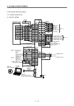
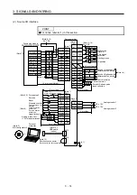
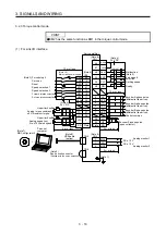
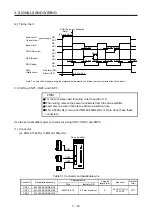
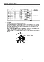
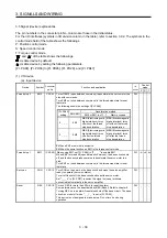
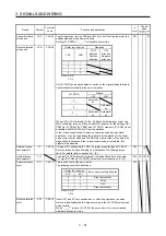
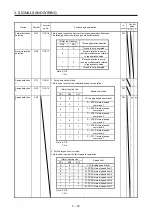
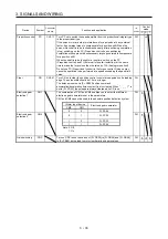
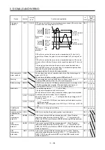
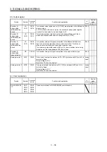
(2) Timing chart
95 ms
95 ms
RD (Ready)
RES (Reset)
SON (Servo-on)
OFF
ON
OFF
ON
ON
OFF
Base circuit
OFF
ON
power supply
OFF
ON
10 ms
5 ms
10 ms
10 ms
5 ms
10 ms
5 ms
10 ms
(2.5 s to 3.5 s)
SON (Servo-on) accepted
Main circuit
Control circuit
Alarm (OFF)
No alarm (ON)
ALM
(Malfunction)
2.5 s to 3.5 s
(Note)
Note. The time will be longer during the magnetic pole detection of a linear servo motor and direct drive motor.
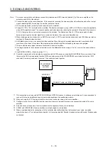
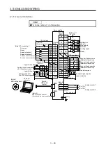
3.3.3 Wiring CNP1, CNP2, and CNP3
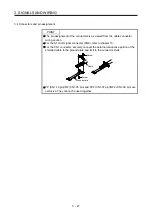
POINT
For the wire sizes used for wiring, refer to section 11.9.
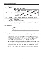
When wiring, remove the power connectors from the servo amplifier.
Insert only one wire or ferrule to each wire insertion hole.
MR-J4-500A(-RJ) or more and MR-J4-500A4(-RJ) or more do not have these
connectors.
Use the servo amplifier power connector for wiring CNP1, CNP2, and CNP3.
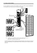
(1) Connector
(a) MR-J4-10A(-RJ) to MR-J4-100A(-RJ)
CNP2
CNP1
CNP3
Servo amplifier
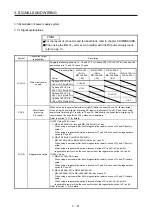
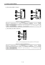
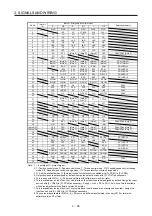
Table 3.1 Connector and applicable wire
Connector Receptacle
assembly
Applicable wire
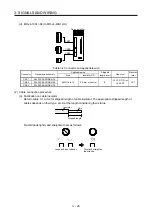
Stripped
length [mm]
Open tool
Manufac
turer
Size Insulator
OD
CNP1 06JFAT-SAXGDK-H7.5
AWG 18 to 14
3.9 mm or shorter
9
J-FAT-OT (N) or
J-FAT-OT
JST
CNP2 05JFAT-SAXGDK-H5.0
CNP3 03JFAT-SAXGDK-H7.5
Summary of Contents for MR-J4-100A(-RJ)
Page 19: ...10 MEMO ...
Page 75: ...1 FUNCTIONS AND CONFIGURATION 1 56 MEMO ...
Page 83: ...2 INSTALLATION 2 8 MEMO ...
Page 159: ...3 SIGNALS AND WIRING 3 76 MEMO ...
Page 203: ...4 STARTUP 4 44 MEMO ...
Page 351: ...7 SPECIAL ADJUSTMENT FUNCTIONS 7 40 MEMO ...
Page 365: ...8 TROUBLESHOOTING 8 14 MEMO ...
Page 387: ...9 DIMENSIONS 9 22 MEMO ...
Page 403: ...10 CHARACTERISTICS 10 16 MEMO ...
Page 553: ...12 ABSOLUTE POSITION DETECTION SYSTEM 12 30 MEMO ...
Page 567: ...13 USING STO FUNCTION 13 14 MEMO ...
Page 607: ...14 COMMUNICATION FUNCTION MITSUBISHI ELECTRIC GENERAL PURPOSE AC SERVO PROTOCOL 14 40 MEMO ...
Page 639: ...15 USING A LINEAR SERVO MOTOR 15 32 MEMO ...
Page 767: ...18 MR J4 03A6 RJ SERVO AMPLIFIER 18 84 MEMO ...
Page 856: ...APPENDIX App 41 ...
Page 905: ...MEMO ...


