

18. MR-J4-03A6(-RJ) SERVO AMPLIFIER
18 - 46
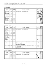
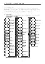
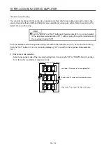
18.4.3 Wiring check
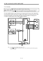
(1) Power supply system wiring
Before switching on the main circuit and control circuit power supplies, check the following items.
(a) Power supply system wiring
The power supplied to the power input terminals (24/0/PM) of the servo amplifier should satisfy the
defined specifications. (Refer to section 18.1.3.)
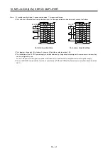
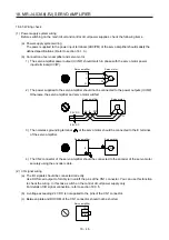
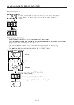
(b) Connection of servo amplifier and servo motor
1) The servo amplifier power output (U/V/W) should match in phase with the servo motor power
input terminals (U/V/W).
Servo amplifier
Servo motor
M
U
V
W
U
V
W
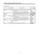
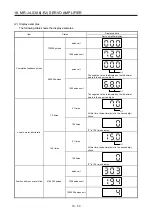
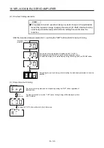
2) The power supplied to the servo amplifier should not be connected to the power outputs (U/V/W).
Otherwise, the servo amplifier and servo motor will fail.
Servo amplifier
Servo motor
24
0 PM
U
V
W
M
24 V DC
48 V DC
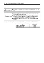
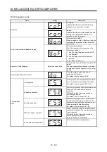
3) The noiseless grounding terminal ( ) of the servo motor should be connected to the E terminal
of the servo amplifier.
Servo amplifier
Servo motor
M
E
4) The CN2 connector of the servo amplifier should be connected to the encoder of the servo motor
securely using the encoder cable.
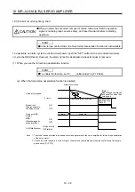
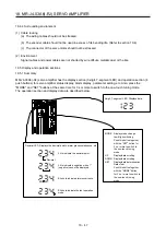
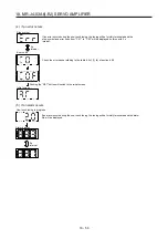
(2) I/O signal wiring
(a) The I/O signals should be connected correctly.
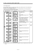
Use DO forced output to forcibly turn on/off the pins of the CN1 connector. You can use this function
to check the wiring. In this case, switch on the control circuit power supply only.
For details of I/O signal connection, refer to section 18.3.5.
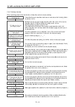
(b) A voltage exceeding 24 V DC is not applied to the pins of the CN1 connector.
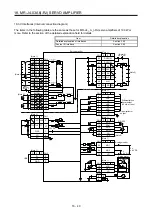
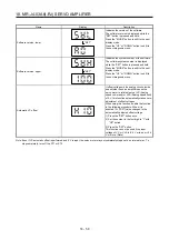
(c) Between plate and DOCOM of the CN1 connector should not be shorted.
Servo amplifier
DOCOM
Plate
CN1
Summary of Contents for MR-J4-100A(-RJ)
Page 19: ...10 MEMO ...
Page 75: ...1 FUNCTIONS AND CONFIGURATION 1 56 MEMO ...
Page 83: ...2 INSTALLATION 2 8 MEMO ...
Page 159: ...3 SIGNALS AND WIRING 3 76 MEMO ...
Page 203: ...4 STARTUP 4 44 MEMO ...
Page 351: ...7 SPECIAL ADJUSTMENT FUNCTIONS 7 40 MEMO ...
Page 365: ...8 TROUBLESHOOTING 8 14 MEMO ...
Page 387: ...9 DIMENSIONS 9 22 MEMO ...
Page 403: ...10 CHARACTERISTICS 10 16 MEMO ...
Page 553: ...12 ABSOLUTE POSITION DETECTION SYSTEM 12 30 MEMO ...
Page 567: ...13 USING STO FUNCTION 13 14 MEMO ...
Page 607: ...14 COMMUNICATION FUNCTION MITSUBISHI ELECTRIC GENERAL PURPOSE AC SERVO PROTOCOL 14 40 MEMO ...
Page 639: ...15 USING A LINEAR SERVO MOTOR 15 32 MEMO ...
Page 767: ...18 MR J4 03A6 RJ SERVO AMPLIFIER 18 84 MEMO ...
Page 856: ...APPENDIX App 41 ...
Page 905: ...MEMO ...


