
7. SPECIAL ADJUSTMENT FUNCTIONS
7 - 38
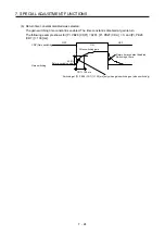
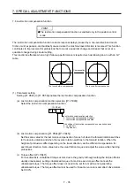
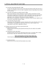
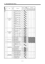
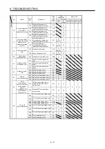
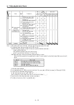
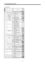
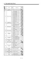
7.7 Super trace control
(1) Summary
In the normal position control, droop pulses are generated against the position control command from
the controller. Using the feed forward gain sets droop pulses at a constant speed to almost 0. However,
droop pulses generated during acceleration/deceleration cannot be suppressed.
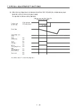
With the ideal model in the servo amplifier, the super trace control enables to set constant speed and
uniform acceleration/deceleration droop pulses to almost 0 that cannot be coped with by the feed
forward gain.
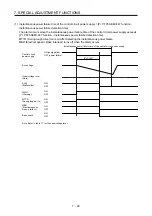
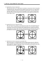
Control
Position command (the same command)
Droop pulses
Normal
control
Time
Servo motor speed
Time
Droop pulses
Droop pulses are always generated.
Feed
forward gain
Time
Servo motor speed
Time
Droop pulses
Droop pulses are generated during acceleration/
deceleration.
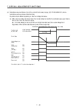
Super trace
control
Time
Servo motor speed
Time
Droop pulses
Droop pulses are almost 0 including the time of
acceleration or deceleration.
Summary of Contents for MR-J4-100A(-RJ)
Page 19: ...10 MEMO ...
Page 75: ...1 FUNCTIONS AND CONFIGURATION 1 56 MEMO ...
Page 83: ...2 INSTALLATION 2 8 MEMO ...
Page 159: ...3 SIGNALS AND WIRING 3 76 MEMO ...
Page 203: ...4 STARTUP 4 44 MEMO ...
Page 351: ...7 SPECIAL ADJUSTMENT FUNCTIONS 7 40 MEMO ...
Page 365: ...8 TROUBLESHOOTING 8 14 MEMO ...
Page 387: ...9 DIMENSIONS 9 22 MEMO ...
Page 403: ...10 CHARACTERISTICS 10 16 MEMO ...
Page 553: ...12 ABSOLUTE POSITION DETECTION SYSTEM 12 30 MEMO ...
Page 567: ...13 USING STO FUNCTION 13 14 MEMO ...
Page 607: ...14 COMMUNICATION FUNCTION MITSUBISHI ELECTRIC GENERAL PURPOSE AC SERVO PROTOCOL 14 40 MEMO ...
Page 639: ...15 USING A LINEAR SERVO MOTOR 15 32 MEMO ...
Page 767: ...18 MR J4 03A6 RJ SERVO AMPLIFIER 18 84 MEMO ...
Page 856: ...APPENDIX App 41 ...
Page 905: ...MEMO ...


