
APPENDIX
App. - 12
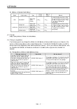
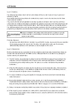
App. 4.4 Electrical Installation and configuration diagram
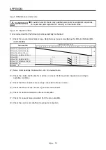
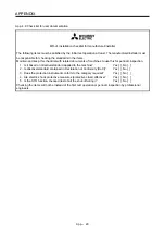
WARNING
Turn off the molded-case circuit breaker (MCCB) to avoid electrical shocks or
damages to the product before starting the installation or wiring.
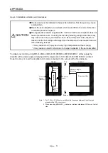
CAUTION
The installation complies with IEC/EN 60204-1. The voltage supply to machines
must be 20 ms or more of tolerance against instantaneous power failure as
specified in IEC/EN 60204-1.
Connecting a servo motor for different axis to U, V, W, or CN2_ of the servo
amplifier may cause a malfunction.
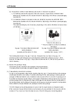
Securely connect the cables in the specified method and tighten them with the
specified torque. Otherwise, the servo motor may operate unexpectedly.
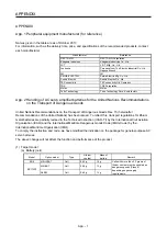
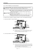
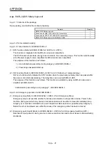
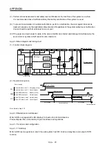
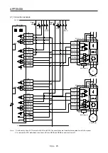
The following shows representative configuration examples to conform to the IEC/EN/UL/CSA standards.
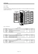
(1) 3-phase input for MR-J4 1-axis servo amplifier
MCCB
or fuse
Controller
STO
Encoder cable
(3-phase
230 V AC)
Power
supply
(3-phase
400 V AC)
Transformer (Note 3)
(star-connected)
(Note 1)
MCCB
or fuse
PE
L11
L21
MC
Servo amplifier
Cabinet side
Machine side
Encoder
Servo motor
L1
C
P+
D
N-
U/V/W/PE
CN2
CN1
CN8
L2L3
To protective equipment
(Thermal signal) (Note 2)
Note 1. When the wire sizes of L1 and L11 are the same, MCCB or fuse is not required.
2. Please use a thermal sensor, etc. for thermal protection of the servo motor.
3. For 400 V class, a step-down transformer is not required.
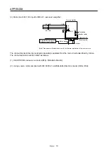
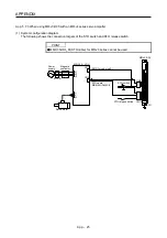
(2) 1-phase input for MR-J4 1-axis servo amplifier
MCCB
or fuse
Controller
STO
Encoder cable
(1-phase
230 V AC)
Power
supply
(3-phase
400 V AC)
Transformer
(star-connected)
(Note 1)
MCCB
or fuse
PE
L11
L21
MC
Servo amplifier
Cabinet side
Machine side
Encoder
Servo motor
L1
C
P+
D
N-
U/V/W/PE
CN2
CN1
CN8
L2L3
(Note 2)
(Note 2)
To protective equipment
(Thermal signal) (Note 3)
Note 1. When the wire sizes of L1 and L11 are the same, MCCB or fuse is not required.
2. When using a 100 V class servo amplifier, step down the power supply voltage to
100 V and connect the main circuit power supply lines to L1 and L2. For 1-phase
200 V AC servo amplifiers, connect the lines to L1 and L3.
3. Please use a thermal sensor, etc. for thermal protection of the servo motor.
Summary of Contents for MR-J4-100A(-RJ)
Page 19: ...10 MEMO ...
Page 75: ...1 FUNCTIONS AND CONFIGURATION 1 56 MEMO ...
Page 83: ...2 INSTALLATION 2 8 MEMO ...
Page 159: ...3 SIGNALS AND WIRING 3 76 MEMO ...
Page 203: ...4 STARTUP 4 44 MEMO ...
Page 351: ...7 SPECIAL ADJUSTMENT FUNCTIONS 7 40 MEMO ...
Page 365: ...8 TROUBLESHOOTING 8 14 MEMO ...
Page 387: ...9 DIMENSIONS 9 22 MEMO ...
Page 403: ...10 CHARACTERISTICS 10 16 MEMO ...
Page 553: ...12 ABSOLUTE POSITION DETECTION SYSTEM 12 30 MEMO ...
Page 567: ...13 USING STO FUNCTION 13 14 MEMO ...
Page 607: ...14 COMMUNICATION FUNCTION MITSUBISHI ELECTRIC GENERAL PURPOSE AC SERVO PROTOCOL 14 40 MEMO ...
Page 639: ...15 USING A LINEAR SERVO MOTOR 15 32 MEMO ...
Page 767: ...18 MR J4 03A6 RJ SERVO AMPLIFIER 18 84 MEMO ...
Page 856: ...APPENDIX App 41 ...
Page 905: ...MEMO ...


