


5. PARAMETERS
5 - 65
No./symbol/
name
Setting
digit
Function
Initial
value
[unit]
Control
mode
P S T
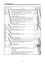
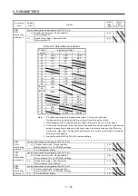
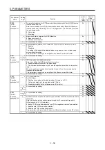
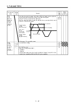
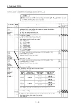
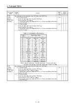
PE50
LMCT
Lost motion
compensation
non-sensitive
band
Set the lost motion compensation non-sensitive band. When the fluctuation of the
droop pulse is the setting value or less, the speed will be 0. Setting can be changed
in [Pr. PE48]. Set the parameter per encoder unit.
This parameter is available with servo amplifiers with software version B4 or later.
Setting range: 0 to 65535
0
[pulse]/
[kpulse]
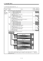
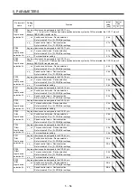
5.2.6 Extension setting 3 parameters ([Pr. PF_ _ ])
No./symbol/
name
Setting
digit
Function
Initial
value
[unit]
Control
mode
P S T
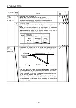
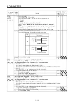
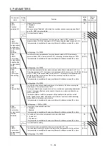
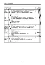
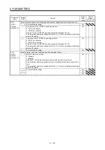
PF09
*FOP5
Function
selection F-5
_ _ _ x Electronic dynamic brake selection
0: Automatic (enabled only for specified servo motors)
2: Disabled
Refer to the following table for the specified servo motors.
0h
Series
Servo
motor
HG-KR
HG-KR053/HG-KR13/HG-KR23/HG-KR43
HG-MR
HG-MR053/HG-MR13/HG-MR23/HG-MR43
HG-SR
HG-SR51/HG-SR52
HG-AK
HG-AK0136/HG-AK0236/HG-AK0336
_ _ x _ For manufacturer setting
0h
_ x _ _
0h
x _ _ _
0h
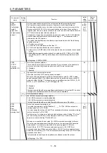
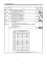
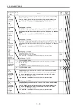
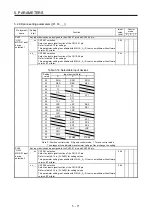
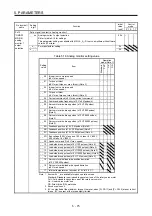
PF15
DBT
Electronic
dynamic
brake
operating
time
Set an operating time for the electronic dynamic brake.
Setting range: 0 to 10000
2000
[ms]
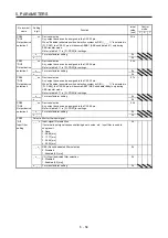
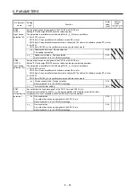
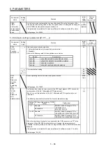
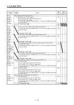
PF18
*STOD
STO
diagnosis
error
detection time
Set the time from when an error occurs in the STO input signal or STO circuit until
the detection of [AL. 68.1 Mismatched STO signal error].
When 0 s is set, the detection of [AL. 68.1 Mismatched STO signal error] is not
performed.
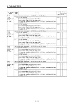
The following shows safety levels at the time of parameter setting.
0
[s]
Setting
value
STO input diagnosis by TOFB
output
Safety level
0
Execute
EN ISO 13849-1 Category 3 PL d,
IEC 61508 SIL 2,
EN 62061 SIL CL2
Not
execute
1 to 60 Execute
EN ISO 13849-1 Category 3 PL e,
IEC 61508 SIL 3, EN 62061 SIL CL3
Not execute
EN ISO 13849-1 Category 3 PL d,
IEC 61508 SIL 2, EN 62061 SIL CL2
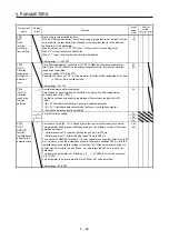
When the short-circuit connector is connected to the CN8 connector, set "0" in the
parameter. When MR-D30 functional safety unit is used, the parameter is not
available. For safety levels at the time of using MR-D30, refer to "MR-D30 Instruction
Manual".
This parameter is available with servo amplifiers with software version C1 or later.
Setting range: 0 to 60
Summary of Contents for MR-J4-100A(-RJ)
Page 19: ...10 MEMO ...
Page 75: ...1 FUNCTIONS AND CONFIGURATION 1 56 MEMO ...
Page 83: ...2 INSTALLATION 2 8 MEMO ...
Page 159: ...3 SIGNALS AND WIRING 3 76 MEMO ...
Page 203: ...4 STARTUP 4 44 MEMO ...
Page 351: ...7 SPECIAL ADJUSTMENT FUNCTIONS 7 40 MEMO ...
Page 365: ...8 TROUBLESHOOTING 8 14 MEMO ...
Page 387: ...9 DIMENSIONS 9 22 MEMO ...
Page 403: ...10 CHARACTERISTICS 10 16 MEMO ...
Page 553: ...12 ABSOLUTE POSITION DETECTION SYSTEM 12 30 MEMO ...
Page 567: ...13 USING STO FUNCTION 13 14 MEMO ...
Page 607: ...14 COMMUNICATION FUNCTION MITSUBISHI ELECTRIC GENERAL PURPOSE AC SERVO PROTOCOL 14 40 MEMO ...
Page 639: ...15 USING A LINEAR SERVO MOTOR 15 32 MEMO ...
Page 767: ...18 MR J4 03A6 RJ SERVO AMPLIFIER 18 84 MEMO ...
Page 856: ...APPENDIX App 41 ...
Page 905: ...MEMO ...


