


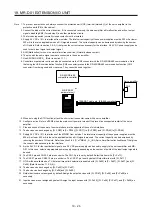
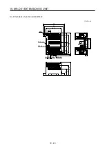

19. MR-D01 EXTENSION I/O UNIT
19 - 31
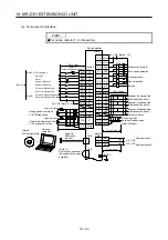
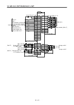
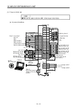
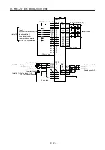
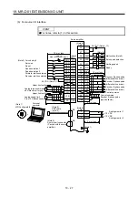
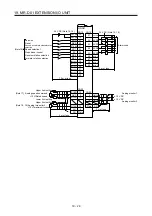
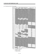
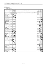
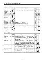
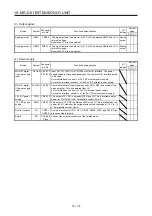
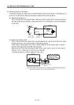
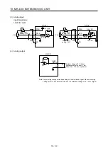
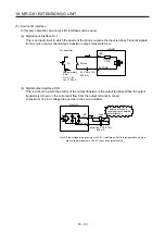
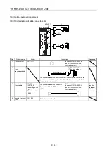
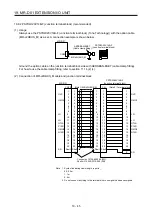
19.5.3 Signal (device) explanations
This section describes the signals (devices) of the MR-D01 extension I/O unit.
The connector pin No. column in the table lists the pin Nos. which devices are assigned to by default.
For the I/O interfaces (symbols in the I/O division column in the table), refer to section 19.5.4 (2).
The symbols in the control mode field of the table shows the followings.
P: Position control mode
S: Speed control mode
T: Torque control mode
" " and " " of the table shows the followings.
: Usable device by default.
: Usable device by setting the following parameters.
[Pr. Po02] to [Pr. Po09], [Pr. Po27], and [Pr. Po28]
Summary of Contents for MR-J4-100A(-RJ)
Page 19: ...10 MEMO ...
Page 75: ...1 FUNCTIONS AND CONFIGURATION 1 56 MEMO ...
Page 83: ...2 INSTALLATION 2 8 MEMO ...
Page 159: ...3 SIGNALS AND WIRING 3 76 MEMO ...
Page 203: ...4 STARTUP 4 44 MEMO ...
Page 351: ...7 SPECIAL ADJUSTMENT FUNCTIONS 7 40 MEMO ...
Page 365: ...8 TROUBLESHOOTING 8 14 MEMO ...
Page 387: ...9 DIMENSIONS 9 22 MEMO ...
Page 403: ...10 CHARACTERISTICS 10 16 MEMO ...
Page 553: ...12 ABSOLUTE POSITION DETECTION SYSTEM 12 30 MEMO ...
Page 567: ...13 USING STO FUNCTION 13 14 MEMO ...
Page 607: ...14 COMMUNICATION FUNCTION MITSUBISHI ELECTRIC GENERAL PURPOSE AC SERVO PROTOCOL 14 40 MEMO ...
Page 639: ...15 USING A LINEAR SERVO MOTOR 15 32 MEMO ...
Page 767: ...18 MR J4 03A6 RJ SERVO AMPLIFIER 18 84 MEMO ...
Page 856: ...APPENDIX App 41 ...
Page 905: ...MEMO ...


