

2. INSTALLATION
2 - 1
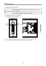
2. INSTALLATION
WARNING
To prevent electric shock, ground each equipment securely.
CAUTION
Stacking in excess of the specified number of product packages is not allowed.
Do not hold the front cover, cables, or connectors when carrying the servo
amplifier. Otherwise, it may drop.
Install the equipment on incombustible material. Installing it directly or close to
combustibles will lead to a fire.
Install the servo amplifier and the servo motor in a load-bearing place in
accordance with the Instruction Manual.
Do not get on or put heavy load on the equipment. Otherwise, it may cause injury.
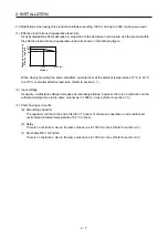
Use the equipment within the specified environment. For the environment, refer to
section 1.3.
Provide an adequate protection to prevent screws and other conductive matter, oil
and other combustible matter from entering the servo amplifier.
Do not block the intake and exhaust areas of the servo amplifier. Otherwise, it
may cause a malfunction.
Do not drop or apply heavy impact on the servo amplifiers and the servo motors.
Otherwise, injury, malfunction, etc. may occur.
Do not install or operate the servo amplifier which have been damaged or have
any parts missing.
When the equipment has been stored for an extended period of time, contact your
local sales office.
When handling the servo amplifier, be careful about the edged parts such as
corners of the servo amplifier.
The servo amplifier must be installed in the metal cabinet.
When fumigants that contain halogen materials such as fluorine, chlorine,
bromine, and iodine are used for disinfecting and protecting wooden packaging
from insects, they cause malfunction when entering our products. Please take
necessary precautions to ensure that remaining materials from fumigant do not
enter our products, or treat packaging with methods other than fumigation (heat
method). Additionally, disinfect and protect wood from insects before packing
products.
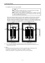
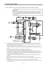
POINT
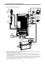
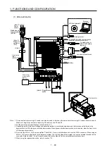
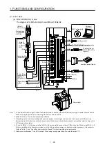
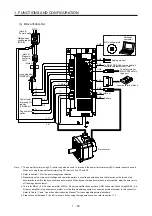
When pulling out CNP1, CNP2, and CNP3 connectors of 100 V class/600 W or
lower 200 V class servo amplifier, pull out CN3 and CN8 connectors
beforehand.
Summary of Contents for MR-J4-100A(-RJ)
Page 19: ...10 MEMO ...
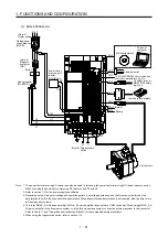
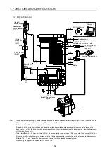
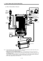
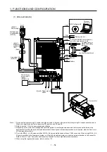
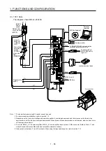
Page 75: ...1 FUNCTIONS AND CONFIGURATION 1 56 MEMO ...
Page 83: ...2 INSTALLATION 2 8 MEMO ...
Page 159: ...3 SIGNALS AND WIRING 3 76 MEMO ...
Page 203: ...4 STARTUP 4 44 MEMO ...
Page 351: ...7 SPECIAL ADJUSTMENT FUNCTIONS 7 40 MEMO ...
Page 365: ...8 TROUBLESHOOTING 8 14 MEMO ...
Page 387: ...9 DIMENSIONS 9 22 MEMO ...
Page 403: ...10 CHARACTERISTICS 10 16 MEMO ...
Page 553: ...12 ABSOLUTE POSITION DETECTION SYSTEM 12 30 MEMO ...
Page 567: ...13 USING STO FUNCTION 13 14 MEMO ...
Page 607: ...14 COMMUNICATION FUNCTION MITSUBISHI ELECTRIC GENERAL PURPOSE AC SERVO PROTOCOL 14 40 MEMO ...
Page 639: ...15 USING A LINEAR SERVO MOTOR 15 32 MEMO ...
Page 767: ...18 MR J4 03A6 RJ SERVO AMPLIFIER 18 84 MEMO ...
Page 856: ...APPENDIX App 41 ...
Page 905: ...MEMO ...


