


5. PARAMETERS
5 - 55
No./symbol/
name
Setting
digit
Function
Initial
value
[unit]
Control
mode
P S T
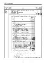
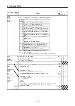
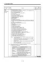
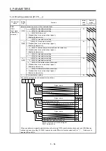
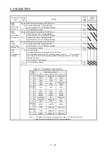
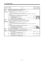
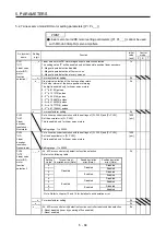
PD03
*DI1L
Input device
selection 1L
Any input device can be assigned to the CN1-15 pin.
_ _ x x Position control mode - Device selection
Refer to table 5.10.
02h
x x _ _ Speed control mode - Device selection
Refer to table 5.10.
02h
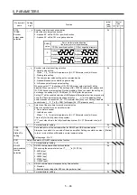
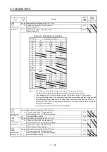
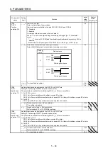
Table 5.10 Selectable input devices
Setting
value
Input device (Note 1)
P
S
T
02
SON
SON
SON
03
RES
RES
RES
04
PC
PC
05
TL
TL
06
CR
07
ST1
RS2
08
ST2
RS1
09
TL1
TL1
0A
LSP
LSP
LSP (Note 3)
0B
LSN
LSN
LSN (Note 3)
0D
CDP
CDP
(Note 4)
0E
CLD
(Note 4)
0F
MECR
20
SP1
SP1
21
SP2
SP2
22
SP3
SP3
23
LOP (Note 2) LOP (Note 2) LOP (Note 2)
24
CM1
25
CM2
26
STAB2
STAB2
Note 1. P: Position control mode, S: Speed control mode, T: Torque control mode
The diagonal lines indicate manufacturer settings. Never change the setting.
2. When assigning LOP (Control switching), assign it to the same pin in all control modes.
3. In the torque control mode, this device cannot be used during normal operation. It can be used
during the magnetic pole detection in the linear servo motor control mode and the DD motor
control mode. Also, when the magnetic pole detection in the torque control mode is completed,
this signal will be disabled.
4. It cannot be set with MR-J4-03A6(-RJ) servo amplifiers.
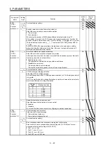
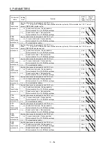
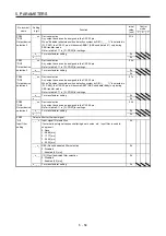
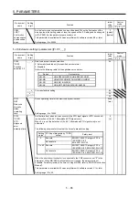
PD04
*DI1H
Input device
selection 1H
Any input device can be assigned to the CN1-15 pin.
_ _ x x Torque control mode - Device selection
Refer to table 5.10 in [Pr. PD03] for settings.
02h
x x _ _ For manufacturer setting
02h
PD05
*DI2L
Input device
selection 2L
Any input device can be assigned to the CN1-16 pin.
_ _ x x Position control mode - Device selection
Refer to table 5.10 in [Pr. PD03] for settings.
00h
x x _ _ Speed control mode - Device selection
Refer to table 5.10 for settings.
21h
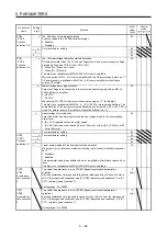
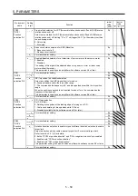
PD06
*DI2H
Input device
selection 2H
Any input device can be assigned to the CN1-16 pin.
_ _ x x Torque control mode - Device selection
Refer to table 5.10 in [Pr. PD03] for settings.
21h
x x _ _ For manufacturer setting
20h
Summary of Contents for MR-J4-100A(-RJ)
Page 19: ...10 MEMO ...
Page 75: ...1 FUNCTIONS AND CONFIGURATION 1 56 MEMO ...
Page 83: ...2 INSTALLATION 2 8 MEMO ...
Page 159: ...3 SIGNALS AND WIRING 3 76 MEMO ...
Page 203: ...4 STARTUP 4 44 MEMO ...
Page 351: ...7 SPECIAL ADJUSTMENT FUNCTIONS 7 40 MEMO ...
Page 365: ...8 TROUBLESHOOTING 8 14 MEMO ...
Page 387: ...9 DIMENSIONS 9 22 MEMO ...
Page 403: ...10 CHARACTERISTICS 10 16 MEMO ...
Page 553: ...12 ABSOLUTE POSITION DETECTION SYSTEM 12 30 MEMO ...
Page 567: ...13 USING STO FUNCTION 13 14 MEMO ...
Page 607: ...14 COMMUNICATION FUNCTION MITSUBISHI ELECTRIC GENERAL PURPOSE AC SERVO PROTOCOL 14 40 MEMO ...
Page 639: ...15 USING A LINEAR SERVO MOTOR 15 32 MEMO ...
Page 767: ...18 MR J4 03A6 RJ SERVO AMPLIFIER 18 84 MEMO ...
Page 856: ...APPENDIX App 41 ...
Page 905: ...MEMO ...


